Rotating mechanism of threader

A technology of slewing mechanism and threading machine, which is applied in the direction of conveyor objects, transportation and packaging, etc., which can solve the problems of high labor intensity, high cost of bulb processing, and low production efficiency

Inactive Publication Date: 2014-01-01
镇江市丹徒区富达灯泡厂
View PDF0 Cites 3 Cited by
  • Summary
  • Abstract
  • Description
  • Claims
  • Application Information

AI Technical Summary

Problems solved by technology

However, the current transfer tools are mainly manual, with low production efficiency, high labo

Method used


Image

  • Rotating mechanism of threader
  • Rotating mechanism of threader

Examples


Embodiment Construction

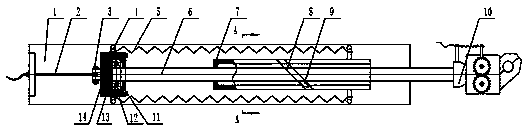
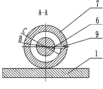
[0012] Depend on figure 1 As we know, the rotary mechanism of the threading machine is composed of the bottom plate 1, the pull wire 2, the shaft fixing seat 14, the return spring 5, the central shaft 6, the shaft sleeve 7, and the manipulator 10. When the pull wire 2 moves to the left, the spring 5 is stretched, Shaft holder 14, central axis 6 also move to the left thereupon, and axle sleeve 7 is fixed. The limit block 9 moves along the trajectory of the spiral groove 8, and the spiral groove 8 has a certain angle, so during the whole movement process, the central axis 6 also makes a circular revolution along the trajectory of the spiral groove 8 while moving to the left Movement, due to the effect of the spring 5, after canceling the force of the pull wire 2, the central shaft 6 moves towards the rebounding direction of the spring, the limit block 9 moves along the spiral track at the same time, and the central shaft 6 moves in the opposite direction. The manipulator 10 is ...


PUM


Abstract

A rotating mechanism of a threader comprises a bottom plate (1), a pull cord (2), spring fixing blocks (4), a shaft holder (14), springs (5), a spiral groove (8), a limit block (9) and a manipulator (10). The rotating mechanism is characterized in that a central shaft (6) moves left, the limit block (9) cycles along the spiral groove (8); meanwhile, under the action of the return springs, the central shaft moves linearly. Under the action of the spiral groove and the limit block, the central shaft rotates while moving linearly, so that the manipulator is rotated. Compared with the traditional simple manipulator which only shifts, the rotating mechanism can rotate and accordingly meet the usage requirements of different applications.

Description

technical field [0001] The invention relates to a rotary mechanism, in particular to a rotary mechanism on a threading machine used for manufacturing automobile bulbs. Background technique [0002] Car bulbs are a must-have component for every car. Car bulbs mainly include headlights, fog lights, turn signals, brake lights, reversing lights, daytime running lights, etc. Therefore, the market prospect of the light bulb is broad. During the manufacturing process of the light bulb, it is necessary to transfer the light bulb from the previous process to the next process. When designing the processing equipment for each process, in order to facilitate the transfer from the previous process to the next process, an automated production line is formed. Therefore A transfer process must be set between the two processes. However, the current transfer tools are mainly manual, with low production efficiency, high labor intensity and low degree of automation, resulting in high process...

Claims


Application Information

Patent Timeline
IPC IPC(8): B65G47/91
Inventor 殷文钦
Owner 镇江市丹徒区富达灯泡厂
Why Eureka
Try Eureka