a cable winch

A towing winch, stranding machine technology, applied in the direction of the hoisting device, the spring mechanism, etc., can solve the problems of slow braking speed of the brake belt, difficult rotation of the drum, and poor resilience of the brake belt, etc. Guaranteed installation requirements and reduced friction

Active Publication Date: 2016-06-01
捷胜海洋工程装备有限公司 +1
View PDF6 Cites 0 Cited by
  • Summary
  • Abstract
  • Description
  • Claims
  • Application Information

AI Technical Summary

Problems solved by technology

This structure has the following problems: the brake is manually operated, and the braking of the drum is achieved through the speed of the manual screw rod and the strength of the worker. The strength of the worker and the speed of the screw rod usually cannot meet the needs of large-load ship machinery. The requirements of the working conditions, and the workers are very dangerous when the screw is hand-cranked, and it is easy to cause safety accidents
[0007] In order to improve safety and adapt to the braking of large winches, the brake bands of many large winches are driven by hydraulic cylinders. Generally, the expansion and contraction of the hydraulic cylinders drive the tension and release of the brake bands. After the brake bands are used for a long time, The resilience of the brake band becomes worse. When the brake band is loosened, due to the gravity of the brake band itself, the lower part of the brake band has loosened the drum, while the upper part of the brake band still hugs the drum tightly, making it difficult to rotate the drum.
[0008] Generally, the production accuracy of the brake band cannot meet the design requirements, or the brake band cannot meet the use requirements due to wear and other reasons after long-term use, which will make the braking speed of the brake band slow

Method used


Image

  • a cable winch
  • a cable winch
  • a cable winch

Examples


Embodiment Construction

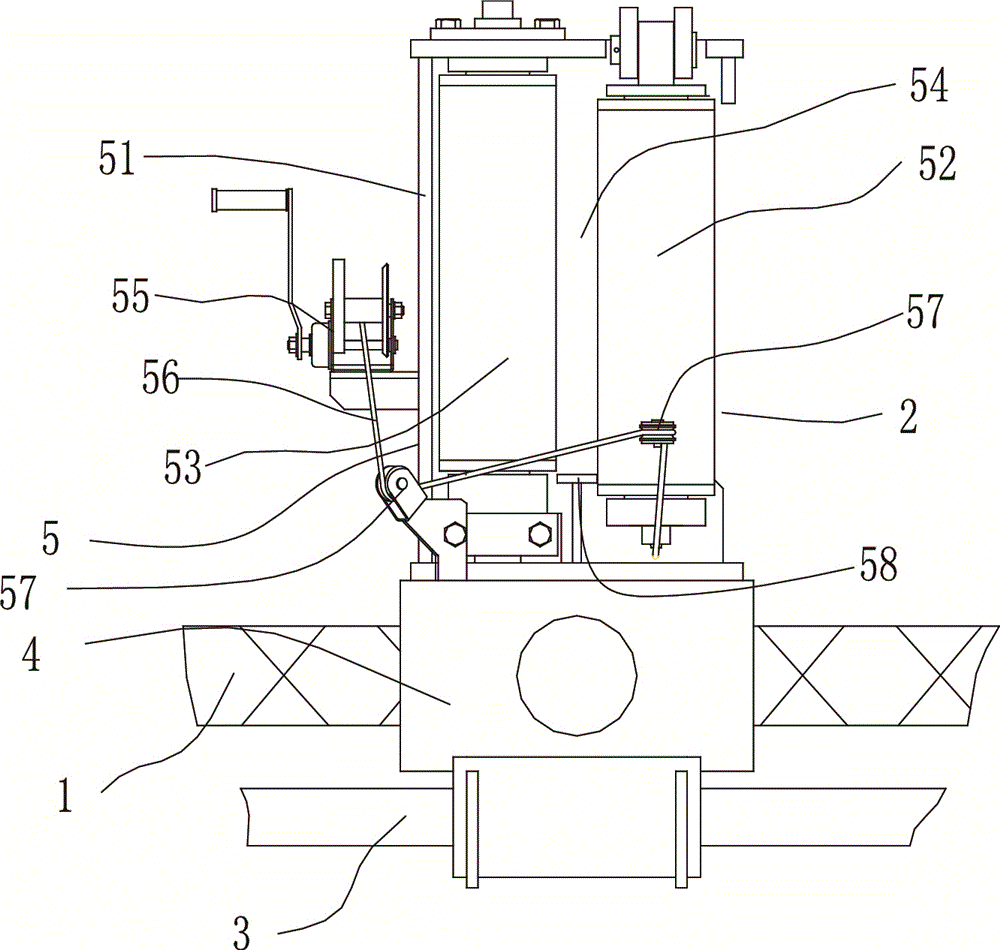
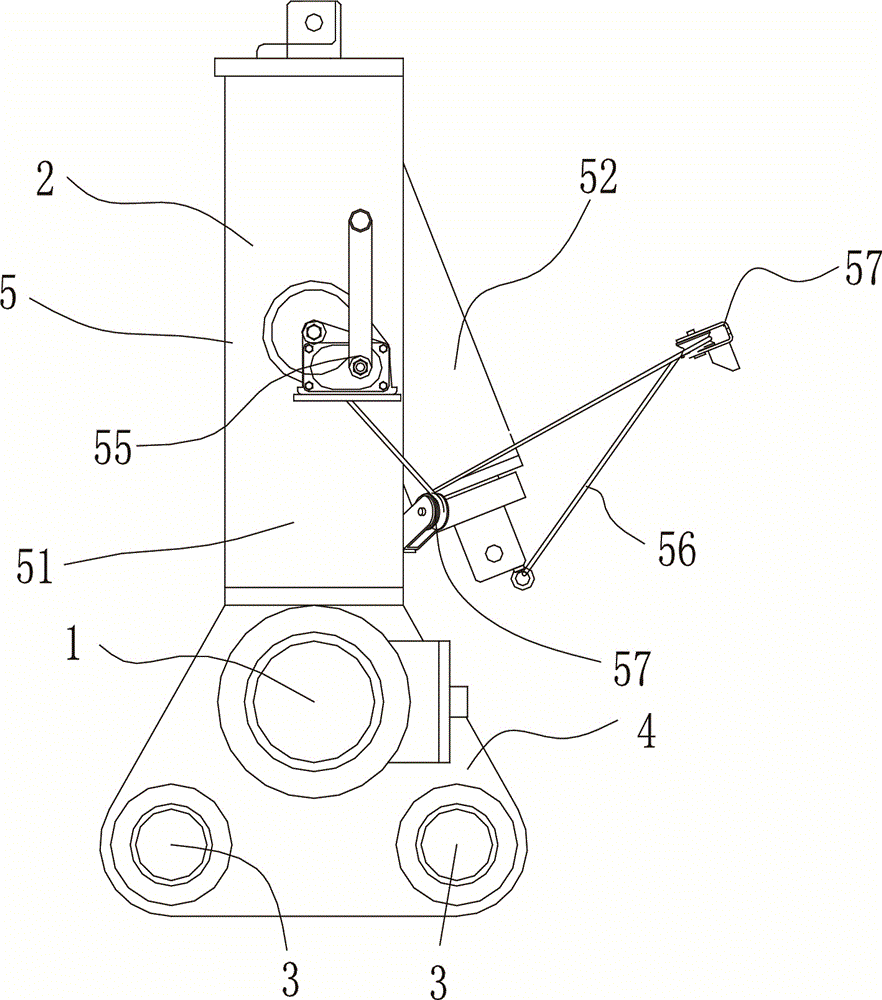
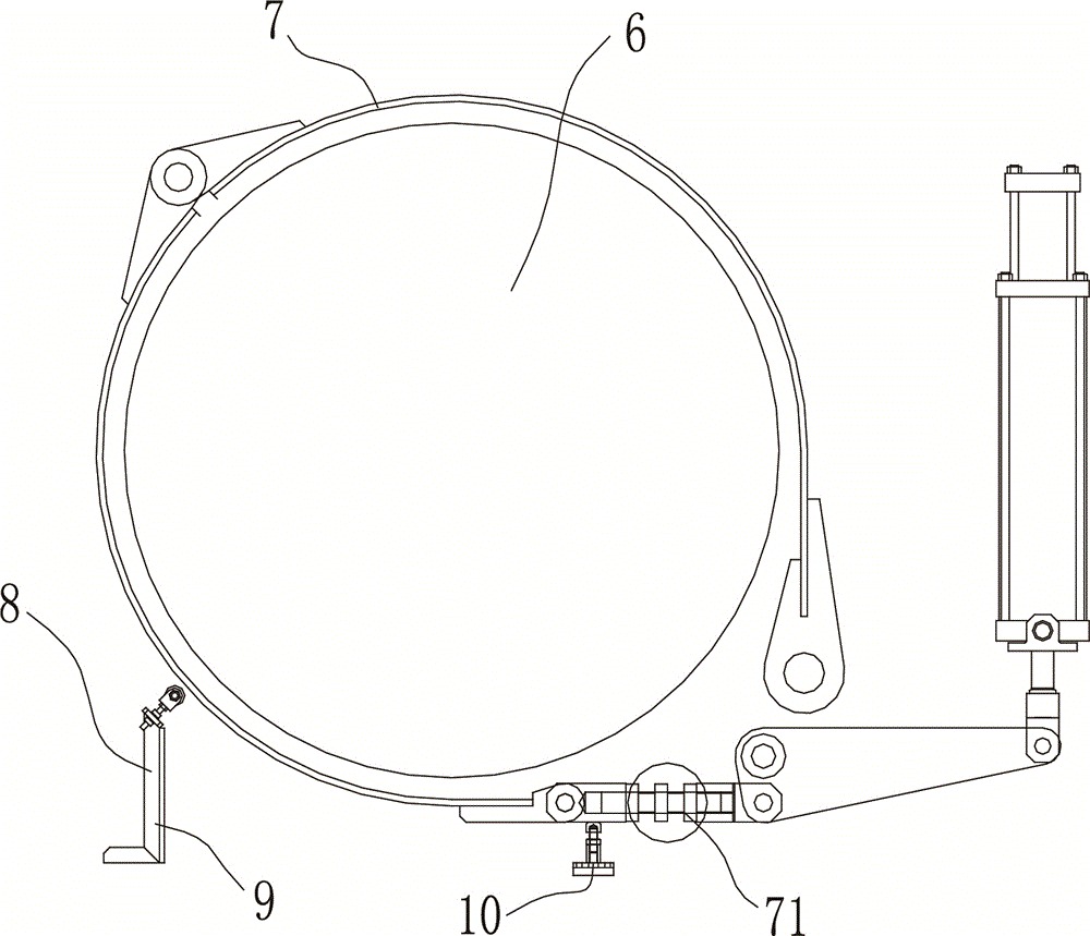
[0025] The present invention will be described in further detail below in conjunction with accompanying drawing and specific embodiment: see Figure 1 to Figure 6 , a tow cable winch, including a cable arrangement, the cable arrangement includes a two-way screw 1, a guide wheel 2, a guide rod 3, the guide wheel 2 includes a base 4 and a guide part 5, the two-way screw 1 and the guide rod 3 The guide rod 3 passes through the base 4 of the guide wheel 2, the two-way screw 1 is parallel to the guide rod 3, and the guide part 5 is composed of a frame body 51 and a first rotating shaft arranged in the frame body 51. 52 and the second rotating shaft 53, the frame body 51, the first rotating shaft 52, and the second rotating shaft 53 form a wire hole 54, the rear side drum 6 of the cable arrangement device, and the outer side of the drum 6 is set There is a brake band 7, the upper end of the first rotating shaft 52 is rotationally connected with the frame body 51, the lower end of th...


PUM


Abstract

The invention discloses a towing winch which comprises a wire arranging device. The upper end of a first rotary shaft of the wire arranging device is rotatably connected with a frame while the lower end of the same is detachably connected with the frame, a jacking device is arranged below a brake belt and comprises a first support, a pulley is arranged on the first support, a pull rod of the brake belt comprises connecting portions on two sides, second threaded holes and third threaded holes opposite to one another and opposite in thread direction are formed in the two connecting portions, third screws are arranged in the second threaded holes and the third threaded holes, and threads on two sides of the third screws are opposite in direction. The upper end of the first rotary shaft of a wire guide wheel is rotatably connected with the frame, so that the first rotary shaft cannot fall down when rotation is needed, a wire can be safely put in or taken out of a wire passing hole, and only one person is needed to push the first rotary shaft to rotate for operation; when the brake belt is about to loosen, the lower side of the brake belt can contact with the jacking device, so that the upper side of the brake belt can quickly be broken away from a drum; the length of the pull rod can be adjusted through the third screws, so that mounting requirements of the brake belt are guaranteed.

Description

technical field [0001] The invention relates to a marine device, in particular to a tow cable winch, which is used for winding or releasing a cable. Background technique [0002] The towline winch is a kind of marine equipment, which is used when the ship is docked and set off. The general towline winch includes a hydraulic motor, a drum, a cable device and a braking device. [0003] The cable arrangement includes brackets, two-way screws, guide wheels, guide rods and other components. The roller and guide rollers are connected by chain transmission. The guide wheels include a base and a guide part. The two-way screw and the guide rod pass through the wires. The base of the wheel, the two-way screw and the guide rod are parallel, and the guide wheel will move back and forth along the radial direction of the two-way screw and the guide rod when the two-way screw rotates. The frame is composed of two rotating shafts in the frame, and the frame and the two rotating shafts form...

Claims


Application Information

Patent Timeline
Patent Type & Authority Patents(China)
IPC IPC(8): B66D1/38B66D1/40B66D1/48
Inventor 贺波叶志坚干卓君支交平陈海涌徐晓吴雪平张国锐
Owner 捷胜海洋工程装备有限公司
Why Eureka
Try Eureka