Rotary oil-gas separator

An oil-gas separator and rotary separation technology, which is applied in the field of refrigeration compressors, can solve the problems of insignificant effect and insufficient oil-gas separation of the oil-gas separator, and achieve the effect of improving the effect of oil-gas separation

Active Publication Date: 2014-01-01
GREE ELECTRIC APPLIANCES INC
View PDF6 Cites 2 Cited by
  • Summary
  • Abstract
  • Description
  • Claims
  • Application Information

AI Technical Summary

Problems solved by technology

[0004] The oil-gas separator of the semi-hermetic screw refrigeration compressor does not fully separate the oil and gas, and the effect is not obvious. How to improve the oil-gas separation efficiency of the screw refrigeration compressor is a key technical problem

Method used


Image

  • Rotary oil-gas separator
  • Rotary oil-gas separator
  • Rotary oil-gas separator

Examples


Embodiment Construction

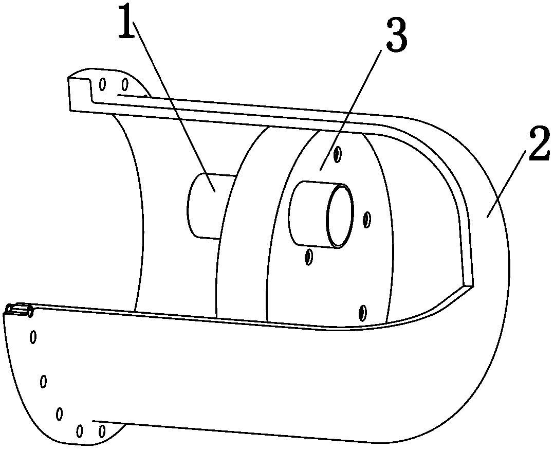
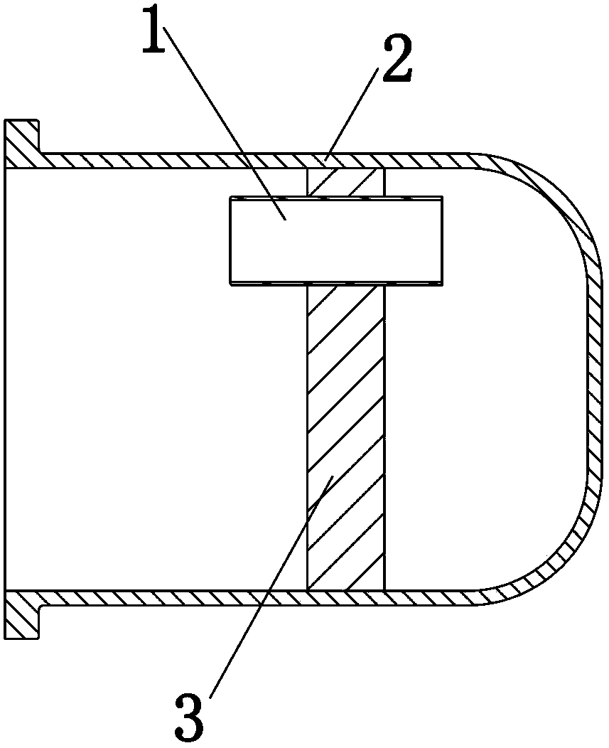
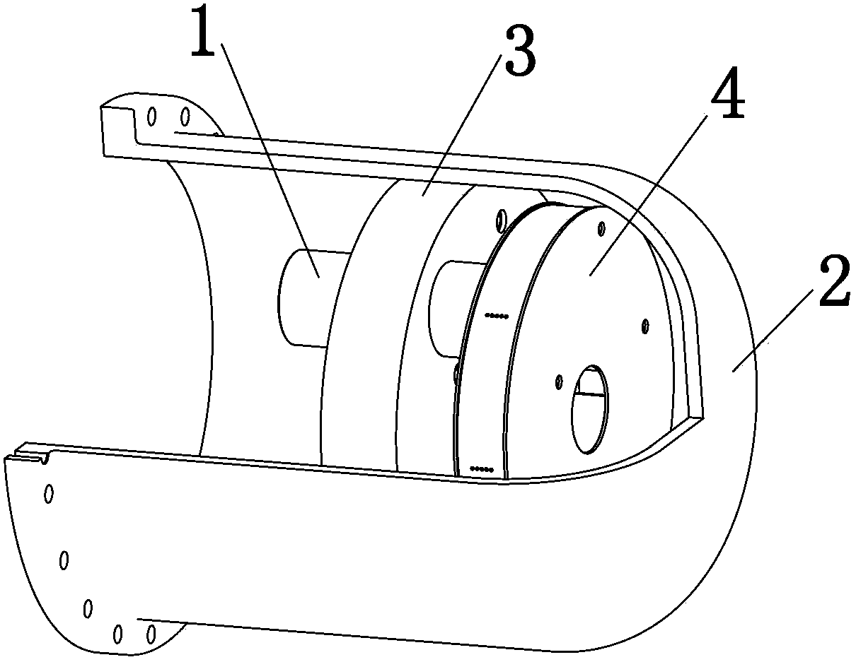
[0030] An embodiment of the rotary oil-gas separator of the present invention, such as Figure 3 to Figure 8 shown.

[0031] The rotary oil-gas separator of the present invention comprises an exhaust pipe 1, an oil-gas separation barrel 2 and an oil-gas separation filter 3;

[0032] The oil-gas separation filter 3 is arranged in the cavity of the oil-gas separation barrel 2;

[0033] The exhaust pipe 1 is arranged on the oil-gas sub-filter 3 and communicates with both sides of the oil-gas sub-filter 3;

[0034] The rotary oil-gas separator also includes a rotary separation device 4;

[0035] The rotary separation device 4 is arranged between the bottom of the oil-gas separation screen 3 and the oil-gas separation barrel 2; the rotary separation device 4 includes a feed port 41, a discharge port 42 and The internal spiral channel 40 of the device 4, one end of the feed port 41 communicates with the spiral channel 40, the other end of the feed port 42 communicates with one en...


PUM

PropertyMeasurementUnit
Diameteraaaaaaaaaa

Abstract

The present invention discloses a rotary oil-gas separator, which comprises an oil-gas separation barrel, a gas exhaust pipe and an oil-gas separation filtering screen, wherein the oil-gas separation filtering screen is arranged inside the cavity of the oil-gas separation barrel, and the gas exhaust pipe is arranged on the oil-gas separation filtering screen and is provided for communicating both sides of the oil-gas separation filtering screen. The rotary oil-gas separator further comprises a rotary separation device, wherein the rotary separation device is arranged between the oil-gas separation filtering screen and the bottom of the oil-gas separation barrel, and comprises a material inlet, a material outlet and a spiral channel arranged inside the rotary separation device, one end of the material inlet is communicated with the spiral channel, the other end of the material inlet is communicated with one end of the gas exhaust pipe, one end of the material outlet is communicated with the spiral channel, and the other end of the material outlet is toward to the bottom of the oil-gas separation barrel. With the rotary oil-gas separator, an oil-gas separation effect of a compressor can be significantly improved.

Description

technical field [0001] The invention relates to a refrigeration compressor, in particular to a rotary oil-gas separator for a refrigeration compressor. Background technique [0002] At present, most screw compressors are oil-injected screws. Lubricating oil is very important to the operation of screw compressors. It can reduce the exhaust temperature of the compressor, and can play the functions of cooling, sealing, lubrication and noise reduction. However, when too much oil is not separated from the compressor, it will be brought into the system, which will greatly reduce the heat transfer performance of the system and affect the performance of the unit. [0003] At present, the structure of the oil-gas separator of the semi-hermetic screw refrigeration compressor is as follows: figure 1 , figure 2 shown. After the compressor gas is discharged from the exhaust pipe 1, it hits the inner wall of the oil-gas separation barrel 2, the direction of the gas changes, and then p...

Claims


Application Information

Patent Timeline
IPC IPC(8): F04C29/02
Inventor 李日华文命清张天翼
Owner GREE ELECTRIC APPLIANCES INC
Why Eureka
Try Eureka