A self-lubricating device for a universal joint shaft

A universal joint shaft, self-lubricating technology, applied in the direction of engine lubrication, engine components, mechanical equipment, etc., can solve problems such as the inability to guarantee the amount of refueling and the indeterminacy of the refueling cycle.

Active Publication Date: 2016-06-29
BAOSHAN IRON & STEEL CO LTD
View PDF5 Cites 0 Cited by
  • Summary
  • Abstract
  • Description
  • Claims
  • Application Information

AI Technical Summary

Problems solved by technology

At present, manual refueling is used for refueling at the slider of the main drive shaft and the cross shaft, and there are two major disadvantages in manual refueling: one is that the amount of refueling cannot be guaranteed, and the other is that the refueling cycle cannot be determined (restricted by the maintenance cycle). It is difficult to fundamentally solve the occurrence of the above faults

Method used


Image

  • A self-lubricating device for a universal joint shaft
  • A self-lubricating device for a universal joint shaft
  • A self-lubricating device for a universal joint shaft

Examples


Embodiment Construction

[0020] The technical solutions of the present invention will be further described below in conjunction with the accompanying drawings and embodiments.

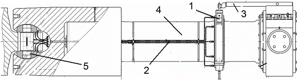
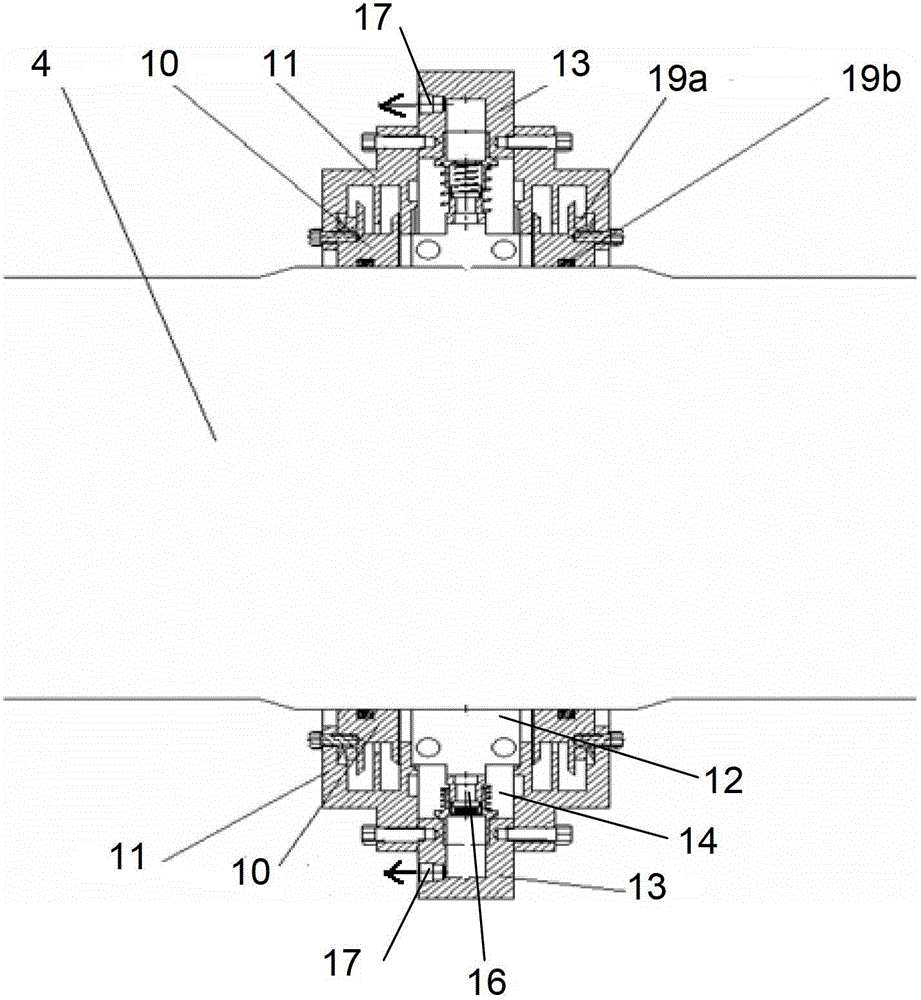
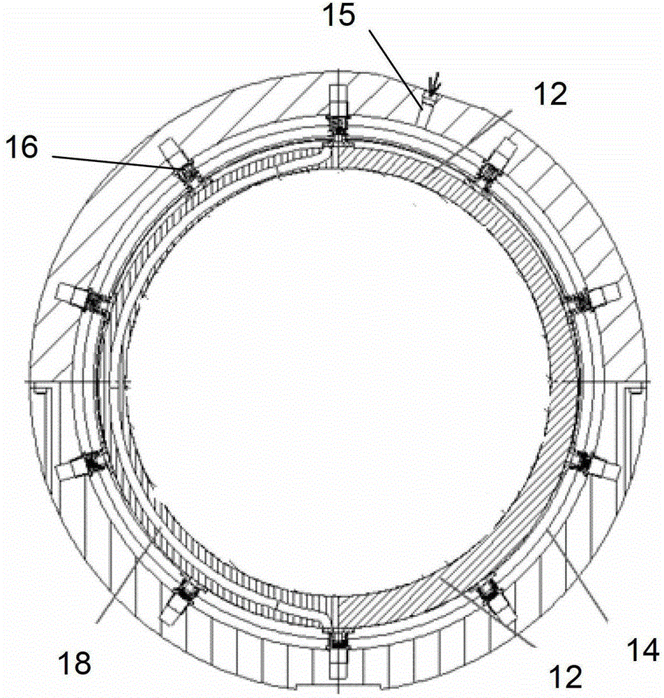
[0021] Please combine Figure 1 ~ Figure 3 As shown, the universal joint shaft self-lubricating device of the present invention mainly includes a self-lubricating body 1 , a lubricating pipeline 2 and a bracket 3 . Among them, the self-lubricating body 1 includes a labyrinth seal ring 10, an end cover 11, an eccentric wheel 12 and a fixed sleeve 13. The eccentric wheel 12 is sleeved on the universal joint shaft 4. After repeated calculations and tests, the eccentric wheel 12 The eccentricity e is designed to be 2 / 5-1 / 2 of the deformation of the return spring 24, the labyrinth seal ring 10 is arranged on both sides of the eccentric wheel 12, the end cover 11 and the labyrinth seal ring 10 are connected by bolts, the fixed sleeve 13 and the The end caps 11 are connected to form an oil storage chamber 14, and the eccentric wheel...


PUM


Abstract

The invention discloses a self-lubricating device for a universal joint shaft. The self-lubricating device includes a self-lubricating body, a lubricating pipeline and a bracket. The self-lubricating body includes a labyrinth sealing ring, an end cover, an eccentric wheel and a fixed sleeve, and the eccentric wheel sleeve Set on the universal joint shaft, the end cover is connected with the palace seal ring, and the fixed sleeve is connected with the end cover to form an oil storage chamber. There are several oil supply pistons on the inner edge of the fixed sleeve, and one end of the oil supply piston passes through the fixed sleeve respectively. The oil outlet of the oil outlet is connected with the lubricating pipeline, and the other end fits the eccentric wheel. There is a radial channel in the eccentric wheel. When the radial channel and the eccentric wheel rotate with the universal joint shaft, the two ends of the radial channel are constantly It communicates with the oil storage chamber or the oil supply piston for oil intake or delivery, and the oil supply piston is rotated and squeezed by the eccentric wheel to supply oil to the lubricating pipeline, and the other end of the lubricating pipeline extends to the fixed position of the universal joint shaft. Heart slider, for its self-lubricating oil.

Description

technical field [0001] The invention relates to shaft lubricating equipment, more specifically, to a self-lubricating device for a universal joint shaft. Background technique [0002] The main transmission shaft of the rolling mill is an important part connecting the prime mover and the working machine. Its damage will cause the machine to stop, and even affect the entire operation line. Therefore, the requirements for its reliability are high, especially for its lubrication. High, insufficient lubrication will greatly reduce fatigue life, causing premature failure or damage. [0003] The main shaft of the roughing mill adopts a cross slider universal joint shaft, while the main shaft of the finishing mill adopts a cross shaft universal joint shaft. The cross slider of the rough rolling mill has broken faults, and the cross shaft of the finishing mill has suffered severe fatigue spalling Faults, the cross shaft bearings have experienced fragmentation faults, and the most fu...

Claims


Application Information

Patent Timeline
Patent Type & Authority Patents(China)
IPC IPC(8): F16N9/02
Inventor 叶秀成丁海绍严伟国施凌王红
Owner BAOSHAN IRON & STEEL CO LTD
Why Eureka
Try Eureka