
LED (light emitting diode) bulb lamp

A technology of LED bulb lamp and LED light source, which is applied in the direction of lighting and heating equipment, semiconductor devices of light-emitting elements, point light sources, etc., can solve the problems of unfavorable productivity control of defective products, slow welding speed, unreliable welding, etc. To achieve the effect of production convenience and product safety, fast welding speed, and reduce welding wire traps

Active Publication Date: 2014-01-01
ZHEJIANG SUNSHINE MEIJIA LIGHTING CO LTD
View PDF4 Cites 6 Cited by
  • Summary
  • Abstract
  • Description
  • Claims
  • Application Information

AI Technical Summary

Problems solved by technology

However, since the thermal conductivity of the aluminum substrate is much greater than that of the driving PCB (FR-4 board), that is to say, since the heat dissipation rate of the aluminum substrate is much greater than that of the FR-4 board, welding wires on the aluminum substrate is much faster than that of the FR-4 board. It is difficult to weld wires on FR-4, so welding wires on aluminum substrates is not only slow in welding speed, but also leads to unreliable welding, resulting in virtual welding, etc., which is extremely detrimental to the improvement of productivity and the control of defective products; on the other hand, Since the positive voltage output wires and negative voltage output wires on the drive power supply components are soft wires, the process of threading wires is required when welding wires, so the connection speed will be affected to a certain extent, thereby affecting productivity

Method used


Image

  • LED (light emitting diode) bulb lamp
  • LED (light emitting diode) bulb lamp
  • LED (light emitting diode) bulb lamp

Examples


Embodiment Construction

[0017] The present invention will be further described in detail below in conjunction with the accompanying drawings and embodiments.

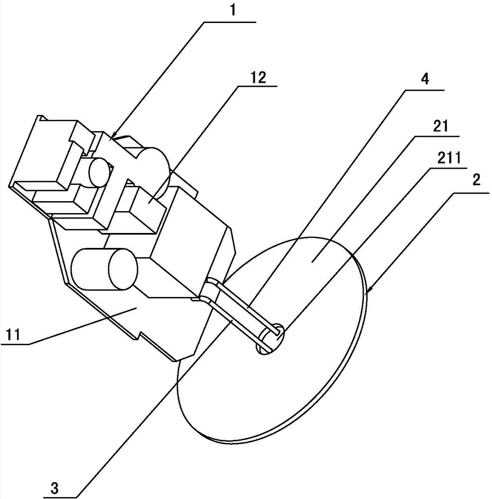
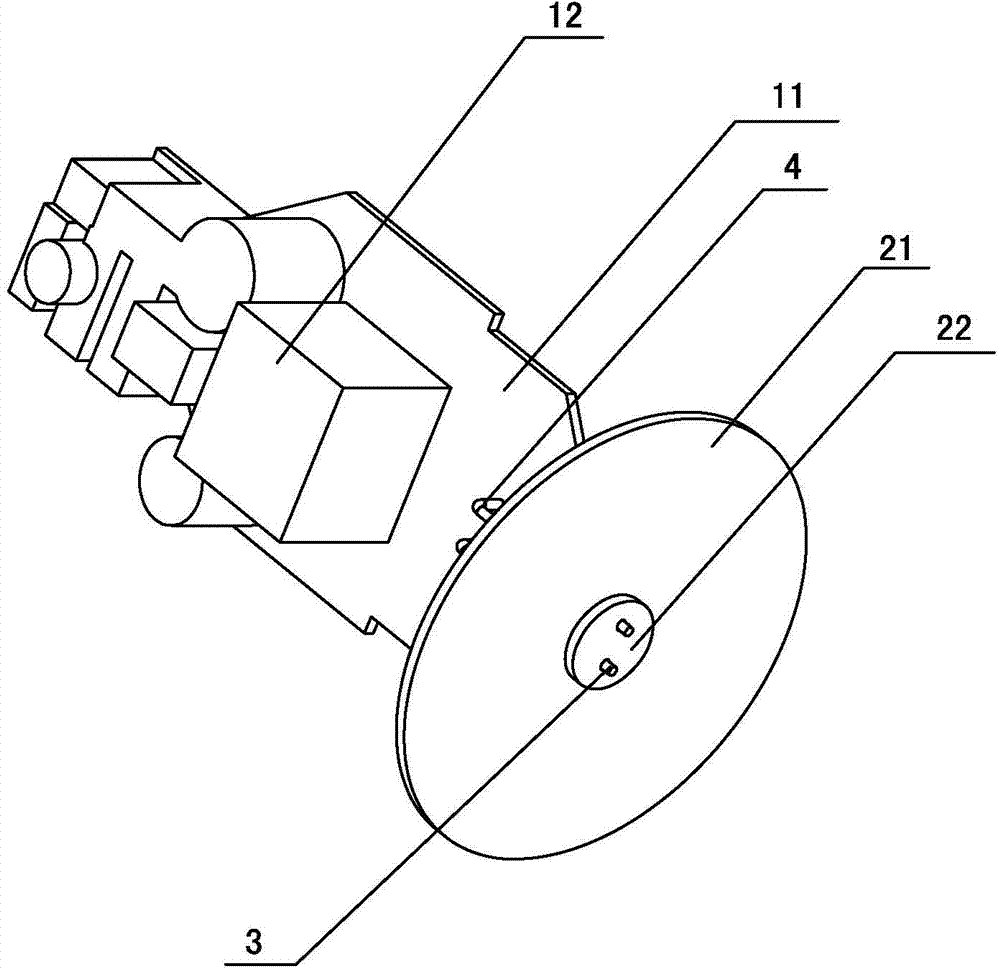
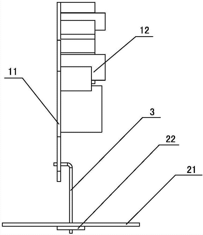
[0018] An LED bulb lamp proposed by the present invention, as shown in the figure, includes a driving power supply assembly 1 and an LED light source assembly 2. The driving power supply assembly 1 is composed of a driving PCB board 11 (FR-4 single-sided PCB board) and connected to The components 12 on the front of the driving PCB 11 are composed. The LED light source assembly 2 is composed of an aluminum substrate 21 and a plurality of LED lamp beads (not shown in the figure) directly attached to the front of the aluminum substrate 21. The driving PCB 11 There are two pin access holes (not shown in the figure), one of which is inserted with an L-shaped first pin 3, and the other pin access hole is inserted with a L-shaped first pin 3. Type of second pin 4, one end of the first pin 3 passes through one of the pin access holes and is welded to ...


PUM


Abstract

The invention discloses an LED bulb lamp. The LED bulb lamp comprises a driving power module and an LED light source module, wherein the driving power module is composed of a driving PCB (printed circuit board) and elements connected to the driving PCB, and the LED light source module is composed of an aluminum substrate and LED beads. A positive voltage output bonding pad of the driving PCB is welded with a first pin, and a negative voltage output bonding pad of the driving PCB is welded with a second pin; a double-faced PCB is adhered to the front surface of the aluminum substrate, a positive voltage input bonding pad on the front surface of the double-faced PCB is welded with the other end of the first pin, and the negative voltage input bonding pad on the front surface of the double-faced PCB is welded with the other end of the second pin; wires which connected all the LED beads in series are distributed on the front surface of the aluminum substrate, and the ends of the wires are respectively connected with a positive voltage output end and a negative voltage output end on the back surface of the double-faced PCB. The LED bulb lamp has the advantages that the first pin and the second pin connect the driving PCB and the double-faced PCB and are welded with the PCB boards rapidly and reliably, so that the occurrence rate of the problem that defective products with faulty welding is prone to occurring due to welding difficulty caused by rapid head dissipation of the aluminum substrate can be reduced.

Description

technical field [0001] The invention relates to a lamp, in particular to an LED bulb lamp. Background technique [0002] With the rapid development of LED lighting technology, more and more LEDs are used as lighting sources. In order to reduce waste, LED bulb lamps that use existing interfaces to replace traditional incandescent lamps for indoor lighting have also emerged one after another. [0003] Generally, LED bulb lamps include two parts: LED light source components and drive power components. LED light source components are usually composed of aluminum substrates and multiple LED lamp beads directly attached to one surface of the aluminum substrates. Through the threading hole of the power line, the other surface of the aluminum substrate is provided with a positive voltage input pad and a negative voltage input pad. The drive power supply assembly is usually composed of a drive PCB (FR-4 board) and mounted on the drive PCB. Composed of components, there are positiv...

Claims


Application Information

Patent Timeline
Patent Type & Authority Applications(China)
IPC IPC(8): F21S2/00F21V19/00F21V21/002F21V23/00F21Y101/02F21K9/232F21V23/06F21Y115/10
Inventor 李阳
Owner ZHEJIANG SUNSHINE MEIJIA LIGHTING CO LTD
Learn More