Fire warning and video monitoring linkage system of direct-current converter station

A DC converter station, video monitoring technology, applied to fire alarms, closed-circuit television systems, alarms, etc., can solve problems such as unfavorable fire emergency management

Active Publication Date: 2014-01-01
CSG EHV POWER TRANSMISSION
View PDF3 Cites 11 Cited by
  • Summary
  • Abstract
  • Description
  • Claims
  • Application Information

AI Technical Summary

Problems solved by technology

[0005] The purpose of the present invention is to provide a fire alarm and video monitoring linkage system in DC converter stations, aiming to solve the problem that the fire alarm system and video monitoring system in the existing DC converter stations are currently independent of each other, which is not conducive to fire alarms. Urgent issues

Method used


Image

  • Fire warning and video monitoring linkage system of direct-current converter station
  • Fire warning and video monitoring linkage system of direct-current converter station
  • Fire warning and video monitoring linkage system of direct-current converter station

Examples


Embodiment 1

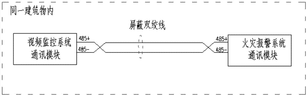
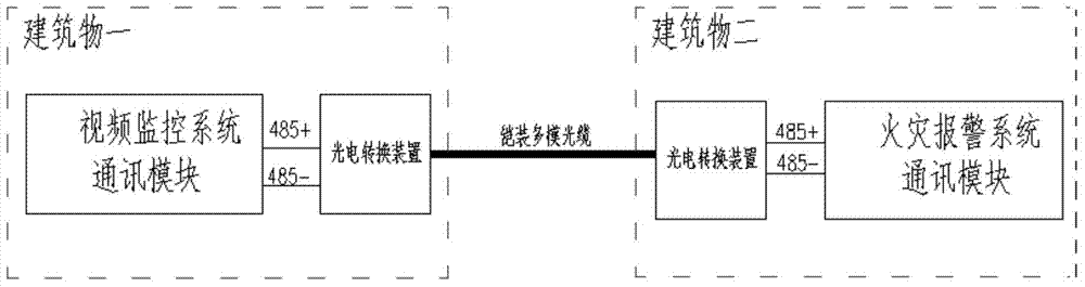
[0045] The RS485 half-duplex communication interface is used, and the RS485 bus is used for communication between the two subsystems that use this interface to exchange information. The physical connection between the two subsystems uses shielded cables or optical cables. When the communication modules of the two subsystems are arranged in the same building (such as the main control building), the shielded twisted pair communication is adopted, and the connection diagram of the physical communication interface is shown in the figure. figure 1 shown. When the communication modules of the two subsystems are arranged in different buildings (for example, the fire alarm host is arranged in the alarm room, and the video surveillance host is arranged in the main control building), the armored multi-mode optical cable is used for communication. Photoelectric conversion device, the photoelectric conversion device is connected with the respective subsystems through the RS485 bus, and th...

Embodiment 2

[0053] The RJ45 network port based on TCP / IP adopts the network communication based on TCP / IP between the two subsystems that use this interface to exchange information. The systems are connected through switches. When the communication modules of the two subsystems are arranged in the same building (such as the main control building), the communication using the super five Ethernet cable is used, and the connection diagram of the physical communication interface is shown in the figure. image 3 shown. When the communication modules of the two subsystems are arranged in different buildings (for example, the fire alarm host is arranged in the alarm room, and the video surveillance host is arranged in the main control building), the armored multi-mode optical cable is used for communication, and the connection diagram of the physical communication interface is shown in the figure. Figure 4 shown.

[0054] Among them, the TCP / IP Modbus communication protocol stipulates as follow...


PUM


Abstract

The invention discloses a fire warning and video monitoring linkage system of a direct-current converter station. The fire warning and video monitoring linkage system comprises a fire warning subsystem, a video monitoring subsystem and a communication module. The fire warning subsystem and the video monitoring subsystem pass through a communication interface of the communication module and conduct linkage communications based on a Modbus communication protocol, and thus linkage warning can be achieved through data analysis. The specific steps are that the fire warning subsystem sends an address code of a fire sensor in a fire alarm occurring place to the video monitoring subsystem, after the video monitoring subsystem receives the address code of the fire sensor, a camera in an actual area corresponding to the address code of the fire sensor is inquired through an address code mapping table, and the video monitoring subsystem is switched to a corresponding camera picture. By means of the fire warning and video monitoring linkage system of the direct-current converter station, the video monitoring system can immediately and automatically push out the monitoring picture of a fire scene when fire alarm happens, and the original function of an original fire warning subsystem and the original function of an original video monitoring subsystem can not be affected.

Description

technical field [0001] The invention relates to the field of electric power transmission, in particular to a fire alarm and video monitoring linkage system of a direct current converter station. Background technique [0002] Generally, DC converter stations are equipped with fire alarm systems and video surveillance systems. Among them, the function of the fire alarm system is to monitor the valve hall, converter transformer, station transformer, main control building, auxiliary control building, relay room, comprehensive building, spare parts warehouse, garage, comprehensive pump room, and alarm room in the converter station. Real-time fire alarm monitoring is carried out in all areas where fire may occur, such as cable interlayers, cable shafts, etc. In the event of a fire, the alarm bell in the station will be activated immediately, an emergency broadcast will be issued, the fire-fighting equipment will be linked, and the elevator will be forced to land. The function of...

Claims


Application Information

Patent Timeline
IPC IPC(8): H04L29/06H04L29/12H04N7/18G08B17/00
Inventor 杨帆龚天森张雪波施世鸿罗继峰孙帮新刘红太宋天奇夏长根陈凯华黄美藩孙刚谷新梅
Owner CSG EHV POWER TRANSMISSION
Why Eureka
Try Eureka