
A mechanical patient transfer vehicle

A transfer vehicle, mechanical technology, applied in the field of patient transfer vehicles, can solve problems such as difficult operation of patient transfer vehicles, achieve the effects of improving work order, simple structure, and avoiding secondary injuries

Active Publication Date: 2015-12-09
上海稼多医疗器械有限公司
View PDF6 Cites 0 Cited by
  • Summary
  • Abstract
  • Description
  • Claims
  • Application Information

AI Technical Summary

Problems solved by technology

[0008] The purpose of the present invention is to overcome the disadvantages of the existing patient transfer vehicles that are difficult to operate, and provide a mechanical patient transfer vehicle. With the technical solution of the present invention, it is not only smart and convenient to operate, requires fewer nursing staff, but also , does not require the patient to move a lot, avoids secondary damage during the transfer process, and has the characteristics of simple structure, low cost, convenient maintenance, stable operation, and low noise

Method used


Image

  • A mechanical patient transfer vehicle
  • A mechanical patient transfer vehicle

Examples


Embodiment

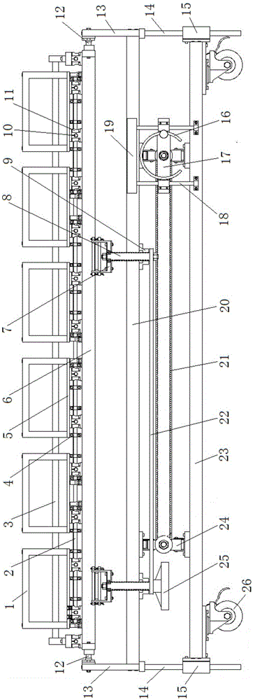
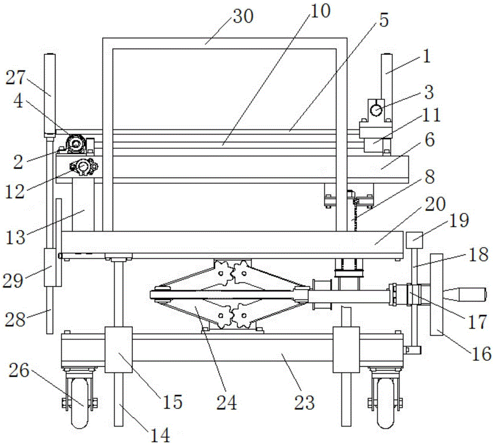
[0044] combine figure 1 and figure 2 , a mechanical patient transfer vehicle of the present embodiment, comprising an upper frame 6, a middle frame 20, a lower frame 23, a lifting device arranged between the lower frame 23 and the middle frame 20, and a lifting device arranged in the middle frame The turning device between the frame 20 and the upper frame 6, the translation device arranged on the upper frame 6 and multiple groups of mutually independent sliding pallets 5, vertical guide mechanisms, universal wheels 26, push-pull handrails 30 and light Axis 2 is located on the same side of the guardrail 27 where:

[0045] The lifting device includes two scissor jacks 24, lifting hand wheel 16, lifting synchronous belt 21, lifting synchronous belt wheel and hand wheel guide mechanism, and the scissor jack 24 is fixed between the lower frame 23 and the middle frame 20 through the mounting plate , used to support the middle frame 20; the lifting hand wheel 16 is connected to th...


PUM


Abstract

The invention discloses a mechanical patient transferring trolley and belongs to the field of special patient transportation tools. The mechanical patient transferring trolley comprises an upper trolley frame, a middle trolley frame, a lower trolley frame, a lifting device arranged between the lower trolley frame and the middle trolley frame, an overturning device arranged between the middle trolley frame and the upper trolley frame, a horizontal moving device arranged on the upper trolley frame and multiple sliding carrying plates which are mutually isolated. A scissor jack is used for ascending and descending the upper trolley frame and the middle trolley frame. A screw nut pair is used for overturning the upper trolley frame. A horizontal guide rail and a rolling bearing are used for horizontally moving the sliding carrying plates which are used for flexibly transferring a patient. The mechanical patient transferring trolley is flexible and convenient to operate, small in number of nursing personnel, needless of greatly moving the patient and capable of avoiding secondary injury in the patient transferring process and has the advantages of being simple in structure, low in cost, convenient to maintain, stable in operation and low in noise.

Description

technical field [0001] The invention relates to a patient transfer vehicle, more specifically, to a mechanical patient transfer vehicle used in a hospital. Background technique [0002] The hospital needs to transfer the patient when the patient needs special examination or special treatment, but at least 3 to 5 people are needed to complete the loading and unloading of the most commonly used stretcher car at present, which will easily lead to many nursing staff in the ward, loud noise and heavy work. Disorder, affecting the recovery of patients. In the past, it was extremely inconvenient to use stretchers, wheelchairs, or a few nurses to carry, hold, and carry them on their backs, especially for critically ill patients, patients with fractures who should not move too much or need to brake, and patients with various drainage tubes left after surgery. In the process, it is inevitable that the range of movements is too large, which will cause problems such as focusing on one ...

Claims


Application Information

Patent Timeline
Patent Type & Authority Patents(China)
IPC IPC(8): A61G1/02
Inventor 田文彤干为民杨辉周海宁张东光袁建梁炀烊胡月王贺贺
Owner 上海稼多医疗器械有限公司
Learn More