
A lock cylinder automatic processing device

An automatic processing and lock cylinder technology, applied in metal processing, manufacturing tools, and other manufacturing equipment/tools, etc., can solve the problems that cannot guarantee the size requirements of the lock cylinder, cannot meet the output and quality, and affect production efficiency. Realize full automation, simple structure and high processing efficiency

Active Publication Date: 2015-09-16
东营市港城热力有限公司
View PDF10 Cites 0 Cited by
  • Summary
  • Abstract
  • Description
  • Claims
  • Application Information

AI Technical Summary

Problems solved by technology

[0002] As the core component of locks, the lock cylinder is widely used in daily necessities such as doors, windows, furniture, and automobiles. With the improvement of people's safety performance requirements, enterprises have put forward higher requirements for the assembly of lock cylinders. At present, the processing of lock cylinders All of them use manual flow operations such as lathes, drilling machines, and milling machines. However, this processing method cannot guarantee the various size requirements of the lock cylinder. It is time-consuming and laborious, and cannot meet the output and quality. Affect production efficiency

Method used


Image

  • A lock cylinder automatic processing device
  • A lock cylinder automatic processing device
  • A lock cylinder automatic processing device

Examples


Embodiment Construction

[0025] The specific implementation manner of the present invention will be described below in conjunction with the accompanying drawings.

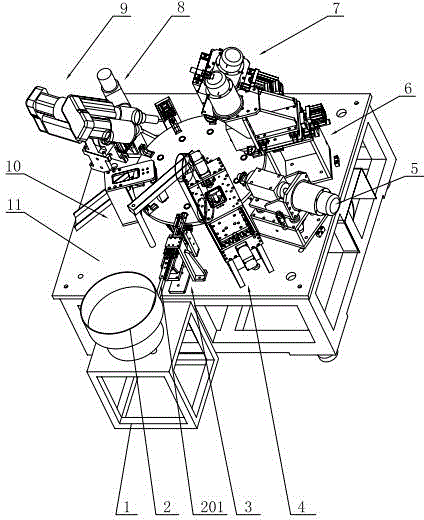
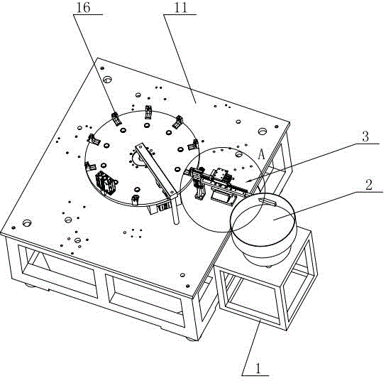
[0026] Such as figure 1 As shown, the present invention comprises a first frame 1 and a second frame 11, and a vibrating tray 2 is set on the first frame 1; The circumferential direction arrangement of the rotating disc assembly is located on the second frame 11, and on the outer periphery of the rotating disc assembly, the feeding unit 3, the drilling unit 4, the first milling unit 5, and the second milling unit are arranged counterclockwise. Unit 6, the third groove milling unit 7, the first oblique hole processing unit 8, the second oblique hole processing unit 9 and the discharge unit 10, the discharge pipe 201 of the vibrating tray 2 extends into the feeding unit 3, and A positioning unit is also installed on the first frame 1 .

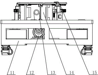
[0027] Such as figure 2 As shown, the rotating disc assembly includes a total motor 12 installed in t...


PUM


Abstract

The invention relates to a lock cylinder automatic machining device which comprises a first machine frame and a second machine frame, wherein a vibration material disc is arranged on the first machine frame, a rotation disc component is arranged on the second machine frame, a plurality of sets of locating dies are arranged in the circumferential direction of the rotation disc component and located on the second machine frame. The periphery of the rotation disc component is provided with a feeding unit, a drilling unit, a first groove milling unit, a second groove milling unit, a third groove milling unit, a first oblique hole machining unit, a second oblique hole machining unit and a discharging unit in the anticlockwise direction. A discharging pipe of the vibration material disc extends into the feeding unit, and the first machine frame is further provided with a locating unit. The lock cylinder automatic machining device has the advantages that the structure is simple, operation is simple and convenient, whole automation of the lock cylinder machining is achieved through all units, machining efficiency is good, quality is high, time and labor are saved, investment on enterprise labor resources is saved, production efficiency is greatly improved, and whole-journey automation of lock cylinder machining is achieved.

Description

technical field [0001] The invention relates to mechanical processing equipment, in particular to an automatic processing device for a lock cylinder. Background technique [0002] As the core component of locks, the lock cylinder is widely used in daily necessities such as doors, windows, furniture, and automobiles. With the improvement of people's safety performance requirements, enterprises have put forward higher requirements for the assembly of lock cylinders. At present, the processing of lock cylinders All of them use manual flow operations such as lathes, drilling machines, and milling machines. However, this processing method cannot guarantee the various size requirements of the lock cylinder. It is time-consuming and laborious, and cannot meet the output and quality. affect production efficiency. Contents of the invention [0003] In view of the above-mentioned existing problems, the applicant has carried out research and improvement, and provides an automati...

Claims


Application Information

Patent Timeline
Patent Type & Authority Patents(China)
IPC IPC(8): B23P23/00B23Q7/00
CPCB23P23/02
Inventor 董仲伟周建武
Owner 东营市港城热力有限公司
Learn More