
Permanent magnet operating mechanism for circuit breaker

A technology of permanent magnet operation and circuit breaker, which is applied in the direction of the power device inside the switch, etc. It can solve the problem of poor matching of the dynamic characteristics of the output characteristics of the circuit breaker contact, the high speed at the end of the opening and closing operation, and the large eddy current of the moving iron core, etc. problem, to achieve the effect of improving the efficiency of the permanent magnet mechanism, reducing the final speed, and reducing the eddy current

Inactive Publication Date: 2016-06-01
SOUTHEAST UNIV
View PDF4 Cites 0 Cited by
  • Summary
  • Abstract
  • Description
  • Claims
  • Application Information

AI Technical Summary

Problems solved by technology

[0003] Purpose of the invention: In order to overcome the deficiencies in the prior art, the present invention provides a permanent magnet operating mechanism for a circuit breaker, which solves the problem of large starting current when opening and closing, long starting time, large difference in starting current when opening and closing, The terminal speed of the opening and closing operation is very large, the eddy current in the moving iron core is large, the air resistance is large, and the output characteristics are not well matched with the dynamic characteristics of the circuit breaker contacts, etc.

Method used


Image

  • Permanent magnet operating mechanism for circuit breaker
  • Permanent magnet operating mechanism for circuit breaker

Examples


Embodiment Construction

[0016] The present invention will be further described below in conjunction with the accompanying drawings.

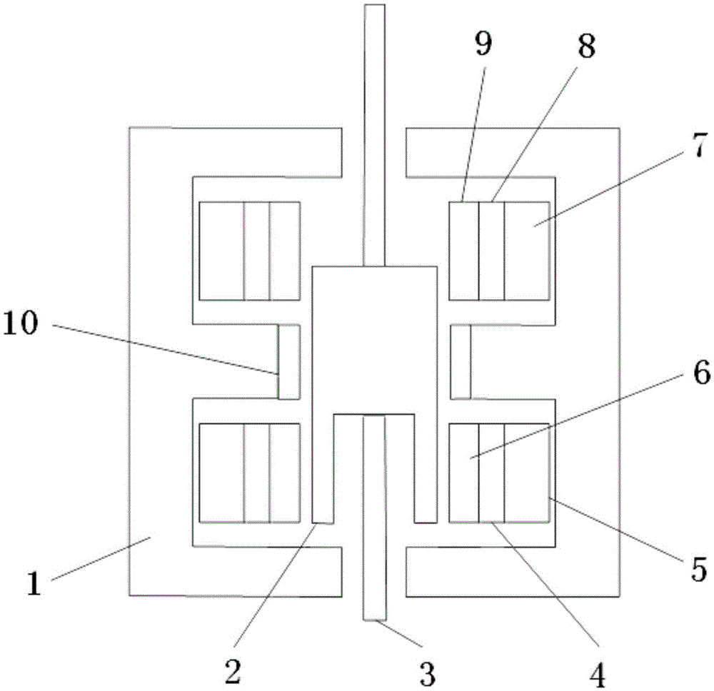
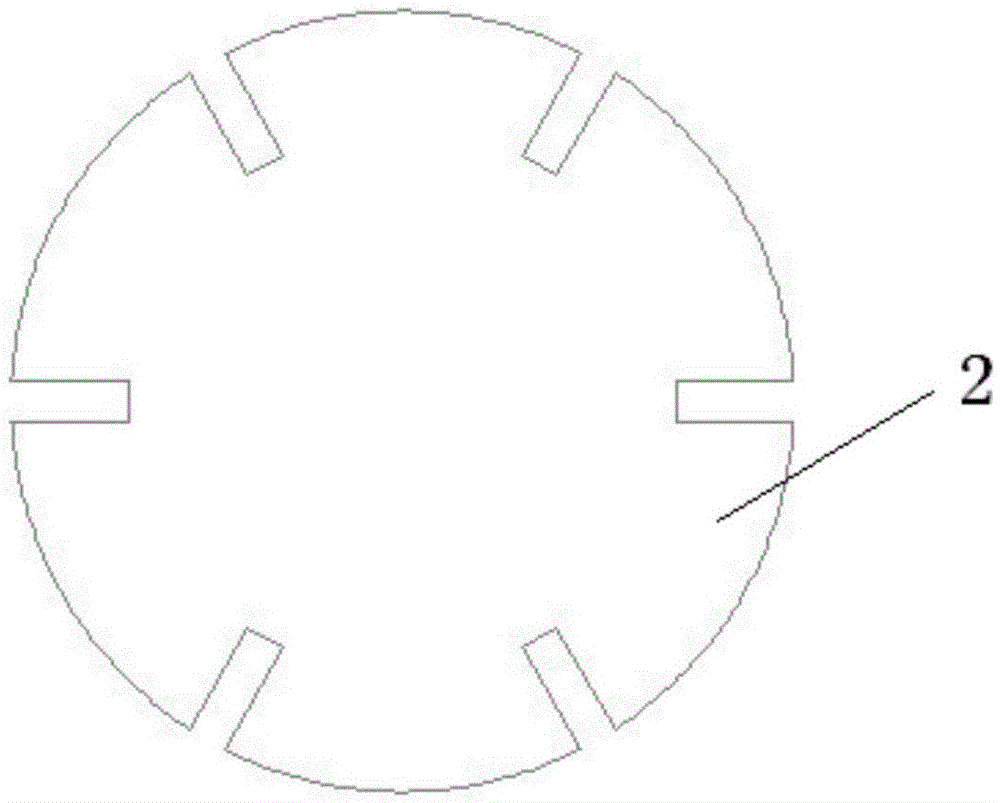
[0017] Such as figure 1 , figure 2 Shown is a permanent magnet operating mechanism for a circuit breaker, including a stator yoke 1, a moving iron core 2, a driving rod 3, a closing buffer coil 9, an auxiliary opening coil 8, a main closing coil 7, a permanent magnet 10, The opening buffer coil 6 , the auxiliary closing coil 4 and the main opening coil 5 ; the moving iron core 2 is placed in the stator yoke 1 , and the driving rod 3 is fixed on the axial direction of the moving iron core 2 . Driven by the driving rod 3, the moving iron core 2 can rotate around the axis, so that the circuit breaker can switch between opening and closing.

[0018] The moving iron core 2 is generally made of low-carbon steel; the lower end surface of the moving iron core 2 is provided with a notch in the axial depth, forming an asymmetric structure on the upper and lower parts of the m...


PUM


Abstract

The invention discloses a permanent magnet operating mechanism for a circuit breaker. The permanent magnet operating mechanism comprises a stator magnet yoke, a movable iron core, a driving rod, a closing buffer coil, an assistant opening coil, a main closing coil, a permanent magnet, an opening buffer coil, an assistant closing coil and a main opening coil, wherein the movable iron core is arranged in the stator magnet yoke; the closing buffer coil, the assistant opening coil and the main closing coil are arranged on the inner side of the upper part of the stator magnet yoke; the permanent magnet is arranged on the inner side of the middle part of the stator magnet yoke; the opening buffer coil, the assistant closing coil and the main opening coil are arranged on the inner side of the lower part of the stator magnet yoke. According to the permanent magnet operating mechanism for the circuit breaker, a starting current is reduced and the starting time is shortened in an opening and closing process; the problem of energy loss when the starting current is larger in difference in the opening and closing process is solved; the end speed of the opening and closing operation of the permanent magnet operating mechanism can be reduced, and the mechanical life of the permanent magnet operating mechanism is prolonged; the eddy current of the movable iron core and the heating loss are reduced, and the efficiency of the permanent magnet operating mechanism is improved.

Description

technical field [0001] The invention relates to a circuit breaker permanent magnet operating mechanism. Background technique [0002] At present, most permanent magnet operating mechanisms of circuit breakers are composed of a stator, a moving iron core, a driving rod, an opening coil, a closing coil, and a permanent magnet, which are symmetrical structures. The opening and closing coils are energized respectively during opening and closing operations. Only one opening and closing coil has a relatively large starting current when opening and closing, and the starting time is long, and the current is also relatively large during the opening and closing process. The large current will cause some problems in coil insulation and temperature rise. The required electromagnetic holding force is different in the opening and closing positions, and the electromagnetic force required in the closing position is larger. The electromagnetic holding force of the traditional symmetrical s...

Claims


Application Information

Patent Timeline
Patent Type & Authority Patents(China)
IPC IPC(8): H01H3/28
Inventor 胡敏强马振琦余海涛陈浩洪立玮施振川
Owner SOUTHEAST UNIV
Learn More