
Centrifugal extractor with defoaming function

A centrifugal extractor and defoaming technology, used in solvent extraction, liquid solution solvent extraction, separation methods, etc., can solve problems such as affecting the efficiency of light-phase transportation, reducing the proportion of infusion pipelines, etc., to increase the proportion and increase the falling time. , to ensure the effect of high efficiency

Pending Publication Date: 2020-03-20
苏州增华新能源科技有限公司
View PDF0 Cites 1 Cited by
  • Summary
  • Abstract
  • Description
  • Claims
  • Application Information

AI Technical Summary

Problems solved by technology

It is known that the light phase will inevitably generate a large number of air bubbles in the process of hitting the shell, which greatly reduces its proportion in the infusion pipeline, thus affecting the subsequent delivery efficiency of the light phase

Method used


Image

  • Centrifugal extractor with defoaming function
  • Centrifugal extractor with defoaming function
  • Centrifugal extractor with defoaming function

Examples


Embodiment Construction

[0025] In the description of the present invention, it should be understood that the orientation or positional relationship indicated by the terms "upper", "lower", etc. is based on the orientation or positional relationship shown in the drawings, and is only for the convenience of describing the present invention and simplifying the description. It is not intended to indicate or imply that the referred device or element must have a particular orientation, be constructed in a particular orientation, and operate in a particular orientation, and thus should not be construed as limiting the invention.

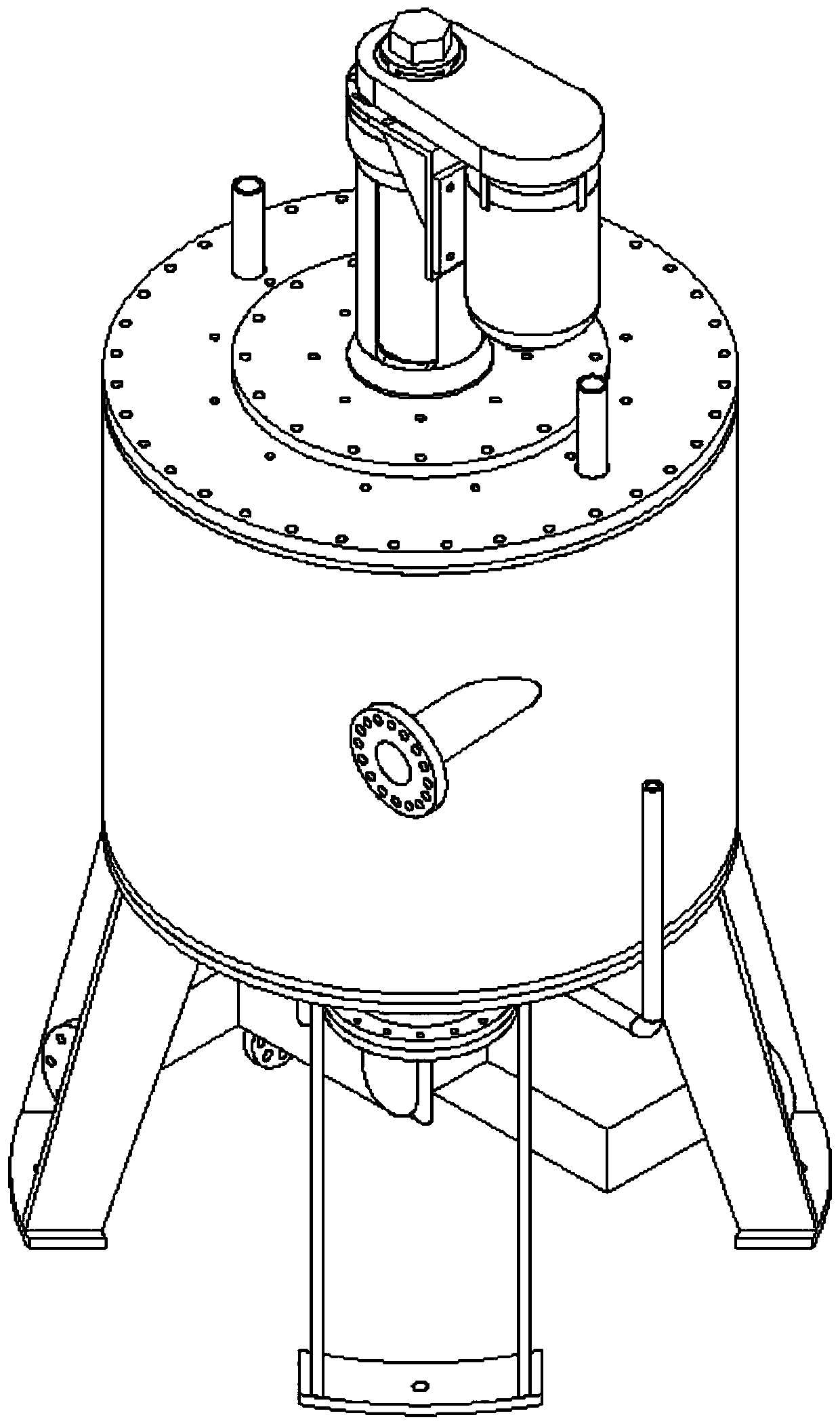
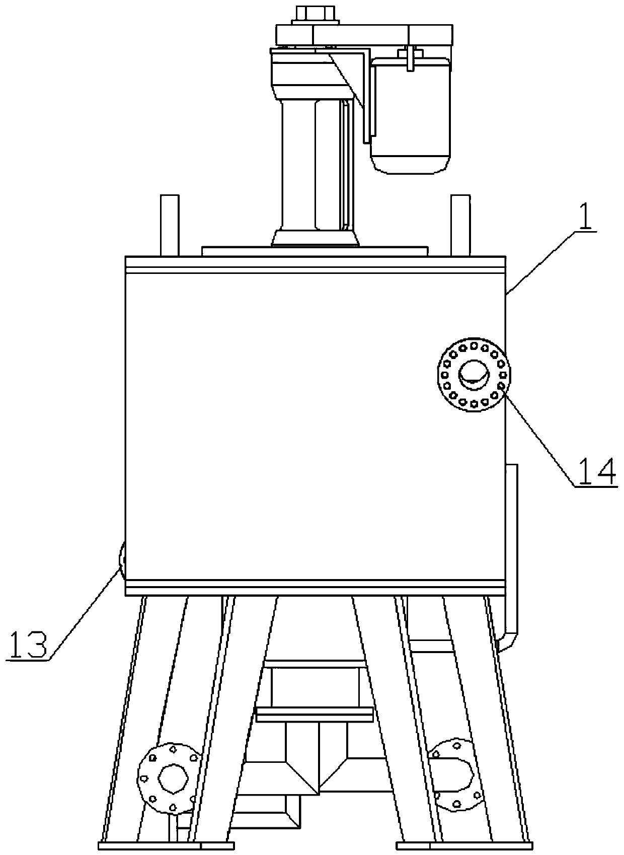
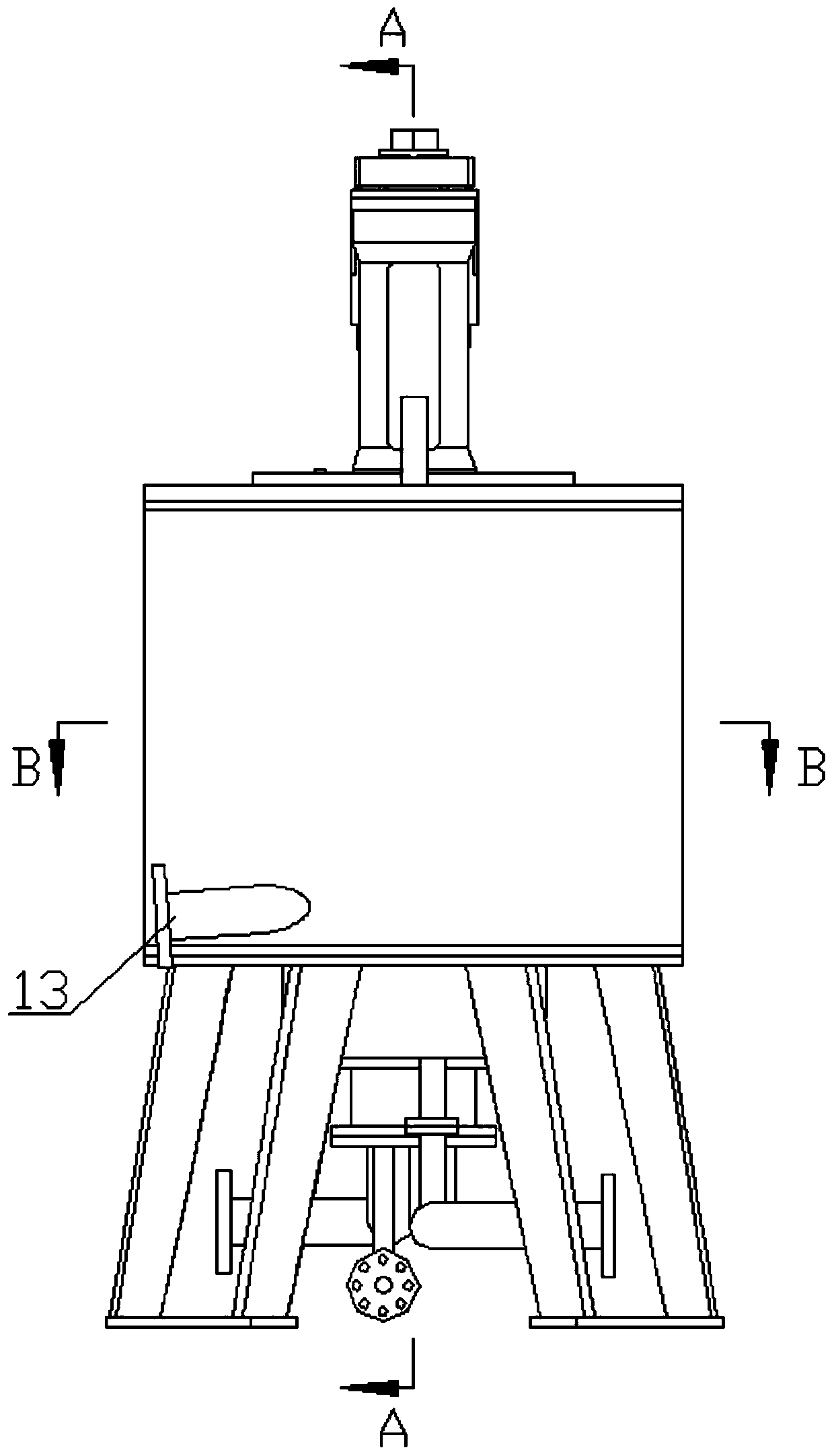
[0026] Below in conjunction with specific embodiment, content of the present invention is described in further detail, figure 1 , figure 2 , image 3 , Figure 4 , Figure 5 The three-dimensional schematic view, front view, left view, A-A sectional view and B-B sectional view of the first embodiment of the centrifugal extractor with defoaming function in the present invention ...


PUM


Abstract

The invention relates to a centrifugal extractor with defoaming function. The centrifugal extractor comprises a shell, a rotary drum extraction unit, a flow dividing cover and a retention delay plate;the flow dividing cover is fixed in an inner cavity of the shell, so that a heavy phase collecting cavity and a light phase collecting cavity are formed in the upper side and the lower side of the flow dividing cover respectively; the rotary drum extraction unit comprises a power shaft and a rotary drum; the rotary drum be driven to rotate circumferentially around the central axis of the rotary drum by the power shaft; a light-phase flow guide port is formed in the side wall of the rotary drum and is positioned below the flow dividing cover; the retention delay plate is internally arranged, is fixed in the light phase collection cavity, and is designed to descend spirally along the inner side wall of the shell to extend to the bottom wall of the shell. According to the above structure, onone hand, a light phase spirally descends along the retention delay plate after impacting the shell, so that the natural defoaming time of the light phase is effectively prolonged; on the other hand,the final speed of the light phase can be effectively reduced, and impact and disturbance of the light phase on the liquid level of the light phase left at the bottom of the shell are reduced.

Description

technical field [0001] The invention relates to the technical field of centrifugal extractor manufacturing, in particular to a centrifugal extractor with defoaming function. Background technique [0002] Centrifugal extraction technology is a practical technology that realizes liquid-liquid two-phase contact mass transfer and phase separation with the help of centrifugal force field. It is a new type of high-efficiency separation technology that combines liquid-liquid extraction and centrifugal technology. Compared with other extraction technologies It has the characteristics of short contact time of two-phase materials, fast phase separation speed, small storage amount in the equipment, and wide operation range. This technology has been used by a large number of scientific researchers in many fields such as hydrometallurgy, pharmaceuticals, wastewater treatment, nuclear energy, petrochemicals, and fine chemicals. [0003] Centrifugal extraction technology is mostly achieve...

Claims


Application Information

Patent Timeline
Patent Type & Authority Applications(China)
IPC IPC(8): B01D11/04B01D17/038B01D19/00B01D19/02
CPCB01D11/0476B01D17/0217B01D19/02B01D19/0042B01D19/0031
Inventor 朱永长雷玉平肖华平赵起
Owner 苏州增华新能源科技有限公司
Learn More