
Insulation heat pipe radiator of explosive-proof structure

A heat pipe radiator and explosion-proof technology, which is applied in the direction of electric solid devices, semiconductor devices, cooling/ventilation/heating transformation, etc., can solve the restrictions, limit the promotion of medium and high voltage electric transmission devices, and cannot meet the insulation requirements of medium and high voltage electric transmission devices and other problems, to achieve the effect of insulation and flameproof, to meet the heat dissipation

Inactive Publication Date: 2014-01-08
张永亮
View PDF4 Cites 2 Cited by
  • Summary
  • Abstract
  • Description
  • Claims
  • Application Information

AI Technical Summary

Problems solved by technology

However, due to the limitation of the insulation level of the power semiconductor device itself, the application of medium and high voltage electric transmission devices in some industries is also limited; because the outer shell of the heat pipe is a closed metal structure, which is a good conductor, the current flameproof equipment used The heat pipe radiator cannot meet the insulation requirements of medium and high voltage electric transmission devices, which limits the promotion of medium and high voltage electric transmission devices

Method used


Image

  • Insulation heat pipe radiator of explosive-proof structure
  • Insulation heat pipe radiator of explosive-proof structure
  • Insulation heat pipe radiator of explosive-proof structure

Examples


Embodiment 1

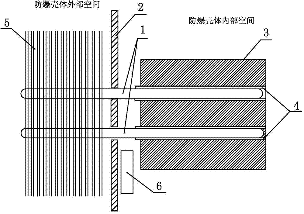
[0024] like figure 1 As shown, the flameproof structure insulated heat pipe radiator of this embodiment includes: a flameproof shell 2, which divides the space into an inner space of the flameproof shell and an outer space of the flameproof shell; The internal space of the body is provided with an internal heat pipe insulation and heat dissipation device. The internal heat pipe insulation heat dissipation device includes a thermally conductive substrate 3, and a substrate hole is arranged inside the thermally conductive substrate 3, and the extension direction of the substrate hole is consistent with the extension direction of the thermally conductive substrate; the internal heat pipe 1 , the internal heat pipe 1 has a heat receiving end and a heat dissipation end, wherein the heat receiving end of the internal heat pipe 1 is penetrated in the substrate hole, and a thermally conductive insulating material 4 is arranged between the hole wall of the substrate hole and the heated ...

Embodiment 2

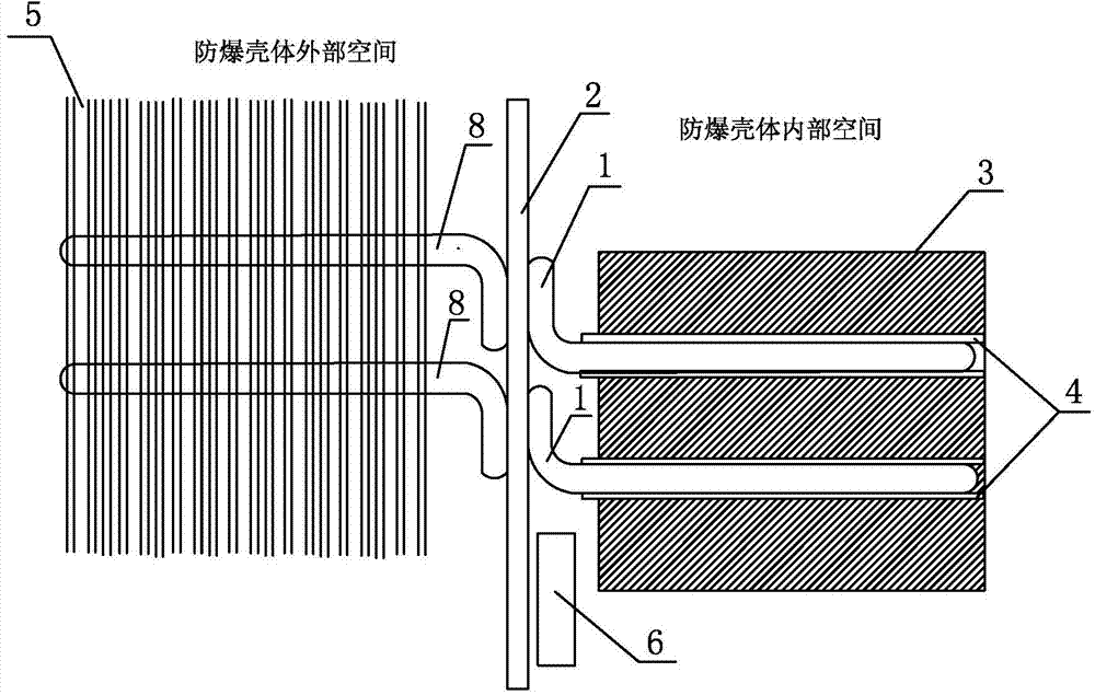
[0029] like figure 2 As shown, the second embodiment is basically the same as the first embodiment, the difference is that the inner heat pipe 1 and the outer heat pipe 8 are arranged in a split type, and both are in a horizontal "L" shape. The heat dissipation end of the inner heat pipe 1 is fixed on the inner wall of the flameproof casing 2 , and the heat receiving end of the outer heat pipe 8 is fixed on the outer wall of the flameproof casing 2 .

[0030] The heat dissipation process of the flameproof structure insulating heat pipe radiator in this embodiment: the power semiconductor device is attached to the thermally conductive substrate 3, and the heat generated by the power semiconductor device is transferred to the heated end of the internal heat pipe 1 through the thermally conductive substrate 3 and the thermally conductive insulating material 4. The vapor and liquid phase change of the medium in the heat pipe 1 transfers the heat to the heat dissipation end of the...

Embodiment 3

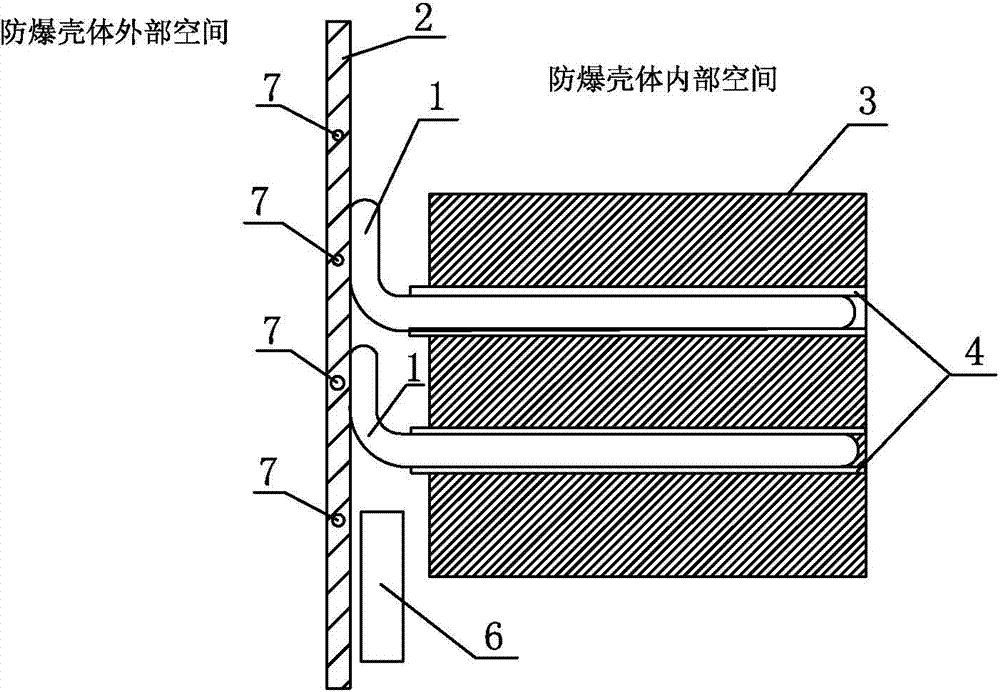
[0032] like image 3 As shown, the difference between Embodiment 3 and Embodiment 1 and Embodiment 2 is that the flameproof structure insulating heat pipe radiator of Embodiment 3 does not have an external heat pipe radiator in the outer space of the flameproof casing, but this embodiment For example, a flameproof shell heat dissipation device is provided on the shell wall of the flameproof shell 2, that is, a fluid heat dissipation channel 7 is provided on the shell wall of the flameproof shell 2, and a heat dissipation fluid circulates in the fluid heat dissipation channel 7.

[0033] The heat dissipation process of the flameproof structure insulating heat pipe radiator in this embodiment: the power semiconductor device is attached to the thermally conductive substrate 3, and the heat generated by the power semiconductor device is transferred to the heated end of the internal heat pipe 1 through the thermally conductive substrate 3 and the thermally conductive insulating mate...


PUM


Abstract

The invention discloses an insulation heat pipe radiator of an explosive-proof structure. The insulation heat pipe radiator comprises an explosive-proof shell. An internal heat pipe insulation heat radiating device is arranged in an internal space of the explosive-proof shell and comprises a heat conduction base plate. A base plate hole is formed inside the heat conduction base plate, and the direction of the base plate hole is consistent with the stretching direction of the heat conduction base plate. A heated end of an internal heat pipe penetrates through the base plate hole. The heat radiating end is fixed to the inner wall of the explosive-proof shell or penetrates through the explosive-proof shell. A heat conduction insulation material and an insulation monitor are arranged between the base plate hole and the heated end of the internal heat pipe. The heat conduction base plate and the internal heat pipe can transfer heat and are mutually insulated through the heat conduction insulation material. The insulation monitor is used for detecting the insulation performance of the heat conduction insulation material. An external heat pipe heat radiating device is arranged outside the explosive-proof shell or an explosive-proof shell heat radiating device is arranged on the shell wall of the explosive-proof shell. The insulation heat pipe radiator of the explosive-proof structure can meet the heat radiating, insulation and explosive-proof requirements, and can be popularized and applied to a high-voltage electric transmission device in the explosive-proof field.

Description

technical field [0001] The present invention relates to the technical field of radiators, in particular to a radiator of an insulating heat pipe with an explosion-proof structure. Background technique [0002] As a heat-conducting element with extremely high thermal conductivity, the heat pipe transfers heat through the vapor and liquid phase change of the medium in the vacuum tube with a certain degree of vacuum at a fully enclosed normal temperature, and has extremely high thermal conductivity; generally, the heated end of the heat pipe is called The hot end and the heat dissipation end are called the cold end. Heat sinks with heat pipes as the core have been widely used in the heat dissipation of power semiconductors. With the development of electric transmission technology using power semiconductors as power devices, medium and high voltage electric transmission devices have become popular. However, due to the limitation of the insulation level of the power semiconduct...

Claims


Application Information

Patent Timeline
Patent Type & Authority Applications(China)
IPC IPC(8): H01L23/427H05K7/20
Inventor 张永亮
Owner 张永亮
Learn More