
Radiating method for high-power LED light source and radiating device for same

A technology of LED light source and heat dissipation device, which is applied in the direction of light source, lighting device, point light source, etc. It can solve the problems of reduced luminous efficiency, poor heat dissipation effect, and inability to give full play to the role of LED light source, and achieve the effect of lowering the temperature

Active Publication Date: 2014-04-23
陈志明 +2
View PDF4 Cites 0 Cited by
  • Summary
  • Abstract
  • Description
  • Claims
  • Application Information

AI Technical Summary

Problems solved by technology

However, the heat dissipation method of the LED light source in the prior art generally adopts the natural air-cooled radiator for heat dissipation. Although the natural air-cooled radiator has the advantages of simple structure and no energy consumption during heat dissipation, due to Its heat dissipation effect is poor, which often makes the LED light-emitting diode as a light source work at its own high temperature, especially the high-power integrated small-area LED light board will work at a temperature higher than 130 ° C, so that the LED light-emitting diode The luminous efficiency of the LED tube is aging ahead of time, which not only increases the energy consumption of the LED light-emitting diode, but also greatly shortens its service life and increases the cost of use.
In addition, the use of existing air-cooled radiators for heat dissipation still has problems such as large volume and heavy weight.
Due to the above-mentioned problems in the heat dissipation method of the existing LED light source, when making LED light source products, the power of the LED light source is usually controlled below 100 watts, which undoubtedly limits the use and promotion of the LED light source
Therefore, the heat dissipation method of the existing LED light source using LED light-emitting diodes as the light source is still not ideal, and the effect of the existing LED light source cannot be fully utilized.

Method used


Image

  • Radiating method for high-power LED light source and radiating device for same
  • Radiating method for high-power LED light source and radiating device for same

Examples


Embodiment Construction

[0015] The present invention will be further described in detail below with reference to the drawings and embodiments.

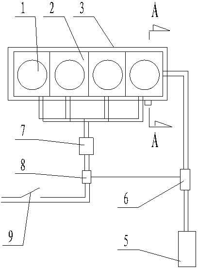
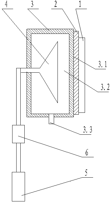
[0016] Embodiments of the present invention: The heat dissipation method of a high-power LED light source of the present invention is mainly used in the occasions where the power of the high-power LED light source 1 installed on the base 2 of the combined lamp board is ≥100W. The back of the combined lamp board base 2 of the power LED light source 1 is directly attached to the heat transfer surface of the radiator 3. In order to achieve a better heat transfer effect, the heat transfer surface of the radiator 3 should be made of iron, aluminum, or copper. The cooling water spray head 4 is installed on the back of the heat transfer surface of the radiator 3, and the cooling water spray head 4 is connected to the cooling water pump 5 through a pipe, so that the cooling water can be delivered to the cooling water through the cooling water pump 5. The water jetting ...


PUM


Abstract

The invention discloses a radiating method for a high-power LED light source and a radiating device for the same. The back of a combined lamp panel base provided with the high-power LED light source is directly mounted on a heat transfer surface of a radiator in a fit manner, and a cooling water sprayer is arranged on the back of the heat transfer surface of the radiator and connected with a cooling water pump through a pipeline, so that cooling water can be delivered to the cooling water sprayer through the cooling water pump and is directly sprayed on the back of the heat transfer surface of the radiator through the cooling water sprayer, and the high-power LED light source mounted on the combined lamp panel base can be radiated and cooled by using the cooling water for cooling the heat transfer surface of the radiator. The radiating method and the radiating device have the advantages of fine radiating effect, suitability for the high-power LED light source with the power higher than 100 watts, and capability of improving the working efficiency of an LED light emitting diode, and are particularly applicable to the high-power LED light source in places such as a wharf, a ship and the like close to a waterside or with a cooling water source.

Description

Technical field [0001] The invention relates to a heat dissipation method and device for a high-power LED light source, in particular to a heat dissipation method and device for a high-power LED light source used in docks, ships and other occasions near water, belonging to LED light-emitting diode lighting heat dissipation technology field. Background technique [0002] At present, because LED light-emitting diodes have the advantages of energy saving, high brightness and small size as light sources, they have been widely used as light sources for lighting. However, the heat dissipation method of the LED light source in the prior art generally uses a natural air-cooled radiator for heat dissipation, and a natural air-cooled radiator is used for heat dissipation. Although on the surface it has the advantages of simple structure and no energy consumption during heat dissipation. Its heat dissipation effect is poor, which often makes the LED light-emitting diode as the light source...

Claims


Application Information

Patent Timeline
Patent Type & Authority Patents(China)
IPC IPC(8): F21V29/02F21Y101/02F21V29/56F21V29/70F21V29/89F21Y115/10
Inventor 陈志明顾伟
Owner 陈志明
Learn More