Panel, method for manufacturing a panel and aircraft

A panel and insulator technology, applied in aircraft parts, air handling equipment, weight reduction, etc., can solve problems such as side panel replacement, achieve the effects of reducing weight, eliminating damage, and reducing risks

Active Publication Date: 2014-01-08
AIRBUS OPERATIONS GMBH
View PDF6 Cites 5 Cited by
  • Summary
  • Abstract
  • Description
  • Claims
  • Application Information

AI Technical Summary

Problems solved by technology

However, this solution has the disadvantage that the entire side panel needs to be replaced if the lining is damaged
The disadvantage is also that wiring cables are routinely installed

Method used


Image

  • Panel, method for manufacturing a panel and aircraft
  • Panel, method for manufacturing a panel and aircraft
  • Panel, method for manufacturing a panel and aircraft

Examples


Embodiment Construction

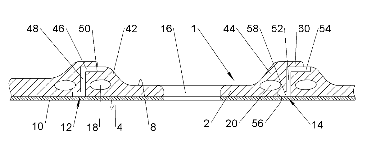
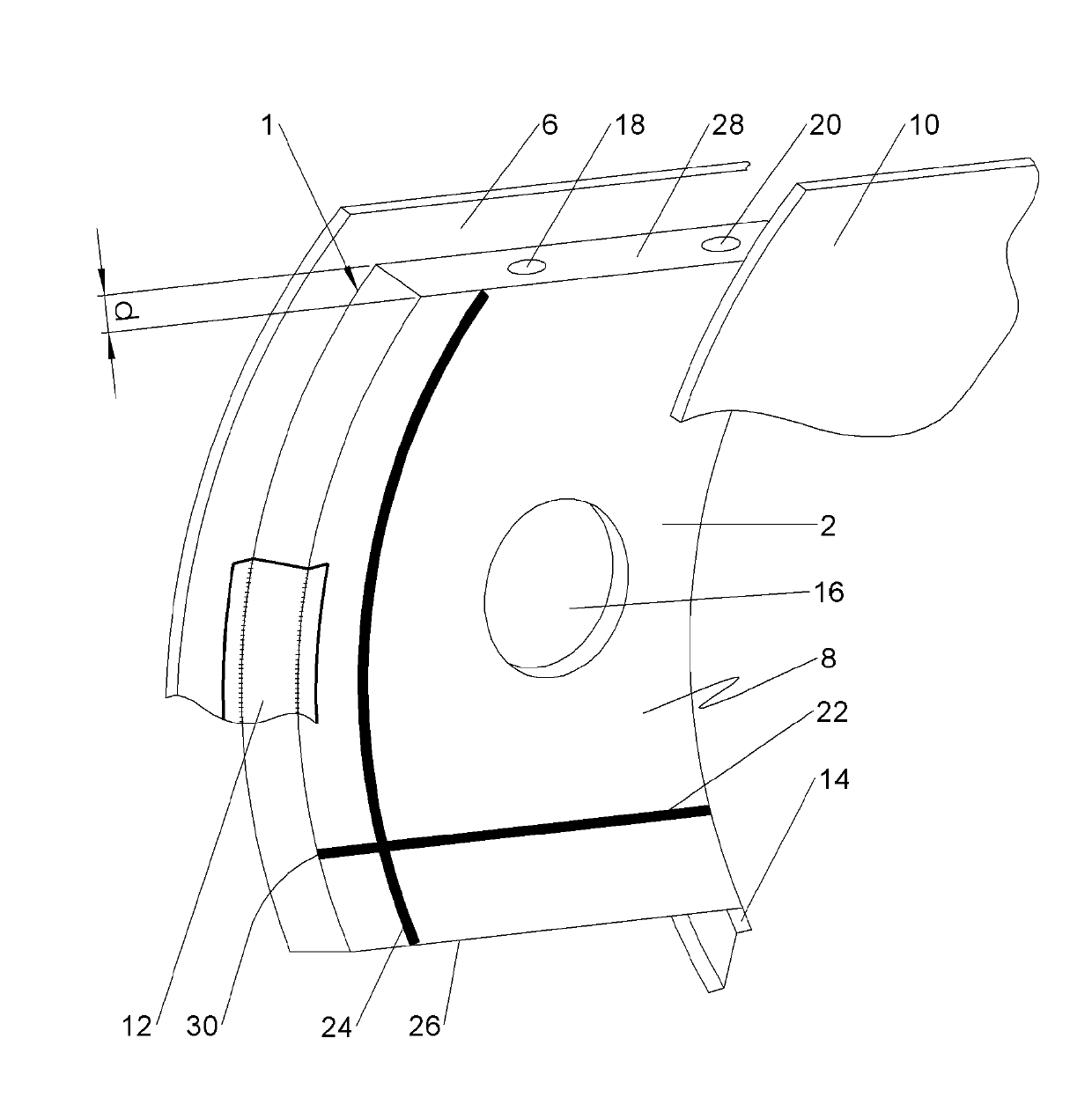
[0025] figure 1 A perspective view of a first exemplary embodiment of a panel 1 of the invention for detachable integration into an aircraft fuselage between a skin 2 and an inner lining 4 (inner trim 4 ) is shown.

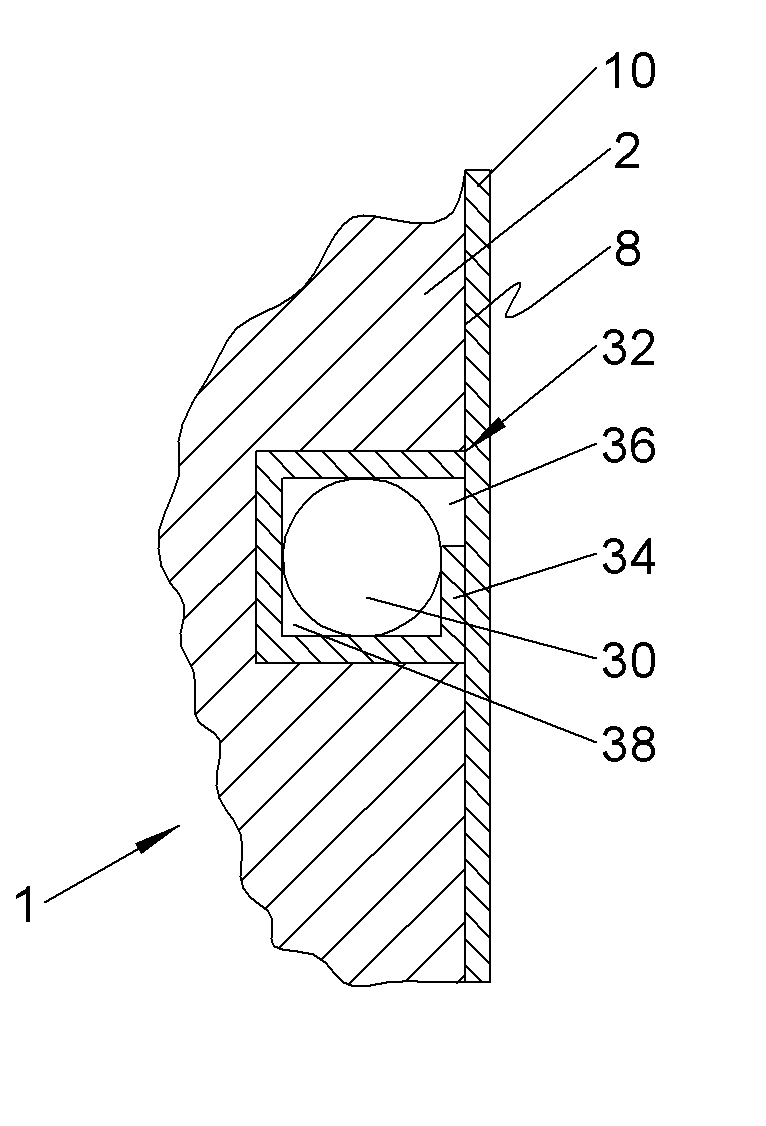
[0026] The panel 1 is characterized by a plate-like insulation or foam 6 of polymer having a constant thickness d. The polymer consists of a rigid foam with closed cells and has thermal, acoustic and fire-resistant properties. The foam 6 has an outer surface 8 in contact with the skin 2 (see image 3 ), and the inner surface 10 covered by the lining 4. It is actively clamped between two circumferential reinforcements such as frames 12 , 14 and follows the curved or spherical shape of the skin 2 . In order to ensure that the foam body 6 contacts the skin 2 flatly with its outer surface 8 , a plurality of not-shown notch-like recesses for receiving longitudinal reinforcements such as stringers are preferably created in the outer surface 8 .

[0027] Furthermore,...


PUM


Abstract

The invention discloses a panel for being detachably arranged between a skin of a means of transport such as, e.g., an aircraft, a motor coach, a railway car or a ship cabin and an interior lining of the means of transport, wherein said panel has a plate-like insulating body that features at least one integrated air-conditioning duct and at least one groove-like cable conduit that is at least sectionally open toward the inner surface, a method for manufacturing a panel of this type, as well as an aircraft with a plurality of such panels.

Description

technical field [0001] The invention relates to a panel for being removably arranged between the skin of a vehicle and the inner lining of the vehicle, to a method for producing a panel of this type, and to an aircraft having a plurality of such panels . Background technique [0002] Means of transportation such as airliners regularly undergo installations of equipment and fittings in which, among others, wiring cables carrying current and signals, clamps for securing wiring cables, insulating mats, and air conditioning ducts are installed . In this case, clips are often initially fastened to the primary structure of the vehicle. The insulating pads are then fastened to the main structure, wherein the pads are provided with corresponding cutouts for introducing clips. Subsequently, the wiring cables are arranged in the clips. The air conditioning lines are then fastened to this primary structure. However, considerable retrofit work is required, since the installation an...

Claims


Application Information

Patent Timeline
Patent Type & Authority Applications(China)
IPC IPC(8): B64C1/06B64D13/00B64C1/40
CPCB64C1/406B64C1/066Y10T29/49Y10T428/24496Y10T428/24479Y10T428/24612Y10T428/24273Y10T428/2457Y02T50/40B64C1/06B64C1/40
Inventor E.弗兰肯贝格尔
Owner AIRBUS OPERATIONS GMBH
Why Eureka
Try Eureka