Intermediate lever

A lever, variable technology, applied in the direction of engine components, machines/engines, mechanical equipment, etc., can solve problems such as high cost

Active Publication Date: 2014-01-08
SCHAEFFLER TECH AG & CO KG
View PDF7 Cites 6 Cited by
  • Summary
  • Abstract
  • Description
  • Claims
  • Application Information

AI Technical Summary

Problems solved by technology

The combination of four rollers with bearings in the final stage is likewise relatively cost-intensive
Because the side walls surround the rollers on the outside, it is possible for the middle lever to be made too wide

Method used


Image

  • Intermediate lever
  • Intermediate lever
  • Intermediate lever

Examples


Embodiment Construction

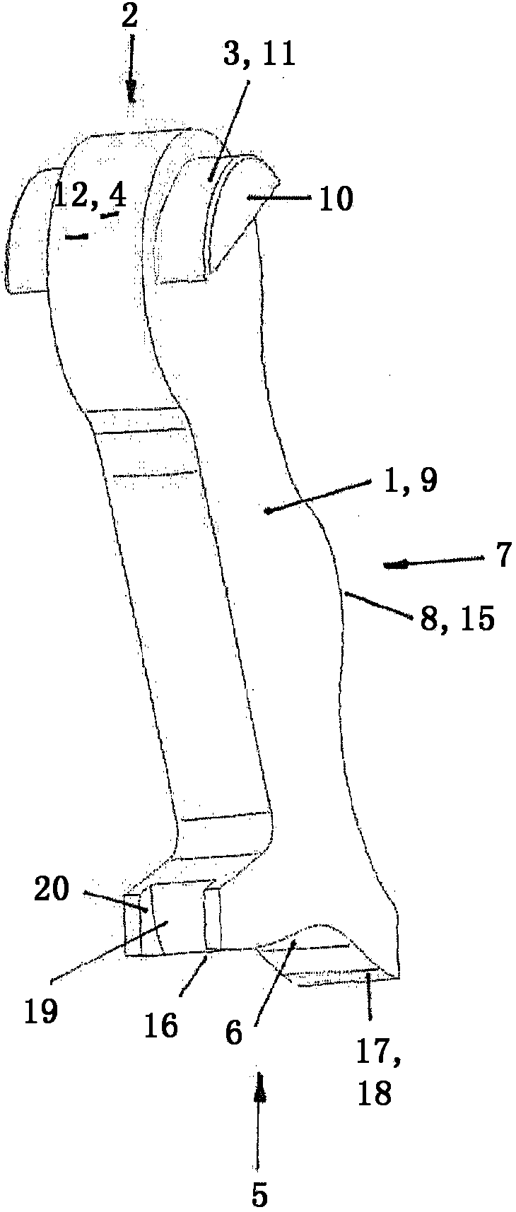
[0018] An intermediate lever 1 for a variable valve drive of an internal combustion engine is shown. The intermediate lever has a closed beam-like geometry and is stamped from sheet steel.

[0019] according to figure 1 , the intermediate lever 1 has, in the region of the positive end 2 , a support surface 3 for the link guide, which is fixed in one piece and is present as a sliding surface. The support surface 3 is composed of two fan-like projections 10 , which lie at a positive end 2 on the outer wall 9 extending parallel to the pivoting direction of the lever. The projections 10 each have an upper peripheral section 11 for the bearing of the link rail. In addition, a contact surface 4 for the cam disc, which is enclosed by the projection 10 and is configured as a sliding surface, extends over this positive end 2 , which extends beyond the projection 10 and serves as a frontal projection of the lever material. It exists from the part 12.

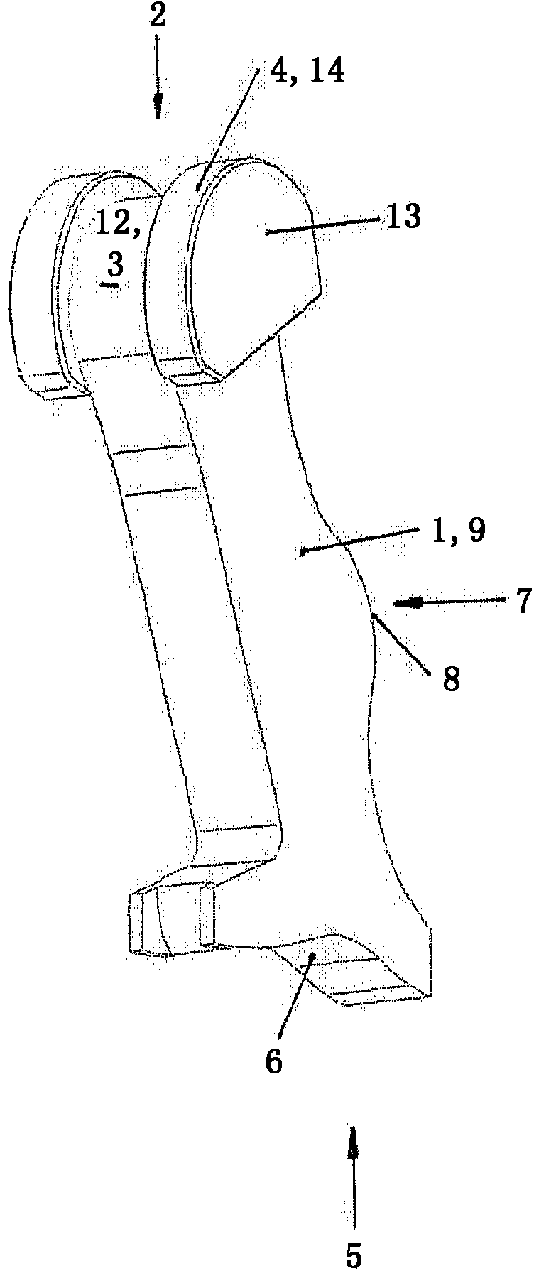
[0020] At the other positive e...


PUM


Abstract

An intermediate lever (1) for a variable valve gear of an internal combustion engine is proposed, said intermediate lever being present in the form of a solid, bar-like compact block, wherein a supporting surface (3) for a slotted guide track and a run-on surface (4) for a cam disc are applied in the region of one end (2), wherein a surface (6) for the variable lifting transfer of a cam onto a tap of a follow-on member sits at a further end (5), wherein a counter-running surface (8) for a lifting cam runs in a section (7) between the ends (2, 5), and wherein the run-on and counter-running surfaces (4, 8) and also the surface (6) for the variable lifting transfer are sliding surfaces.

Description

technical field [0001] The invention relates to an intermediate lever for a variable valve drive of an internal combustion engine, wherein in the region of a positive end a support surface for a link guide rail and an abutment surface for a cam disc are embodied, wherein The surface for transmitting the variable stroke of the cam to the catch of the follower is on the other positive end, and the counter-moving surface for the stroke cam extends in the section between the ends. Background technique [0002] An intermediate lever of this type is known from FIGS. 5 and 6 of DE 10 2006 018 512 A1. The intermediate lever has two beam-shaped side walls. On one positive end, these side walls enclose a total of three rolling bearing rollers, two of which are used as supporting rollers for mating movement on the slideway guide, and the The rollers between the two rollers serve as abutment surfaces for the cam discs. In the middle section, the middle lever has an additional rolling...

Claims


Application Information

Patent Timeline
IPC IPC(8): F01L13/00
CPCF01L13/0063F01L13/0021F01L13/0026F01L2013/0068
Inventor 马蒂亚斯·贝克尔沃尔夫冈·克里斯特根
Owner SCHAEFFLER TECH AG & CO KG
Why Eureka
Try Eureka