Machine tool and method for ejecting workpiece parts

A technology for workpieces and machine tools, applied in the field of sheet metal, can solve the problems of inability to ensure the positioning of the release device and large tolerances of components

Active Publication Date: 2017-10-31
TRUMPF WERKZEUGMASCHINEN GMBH & CO KG
View PDF4 Cites 0 Cited by
  • Summary
  • Abstract
  • Description
  • Claims
  • Application Information

AI Technical Summary

Problems solved by technology

However, the position of the release device or the holding-down device can only be ascertained indirectly (for example by measuring the displacement of the punch)
However, the component tolerances of the hold-down device and the release device are typically so great that in this way it cannot be ensured that the release device is positioned at a defined distance from the upper side of the workpiece.

Method used


Image

  • Machine tool and method for ejecting workpiece parts
  • Machine tool and method for ejecting workpiece parts
  • Machine tool and method for ejecting workpiece parts

Examples


Embodiment Construction

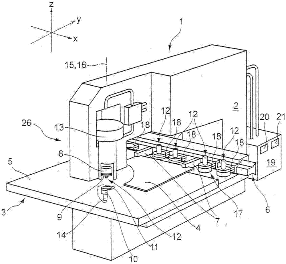
[0033] figure 1 A machine tool 1 is shown for the cutting and / or forming of sheet metal workpieces in the form of a punching / forming machine for processing sheet metal. The punching / forming machine 1 has a C-shaped frame 2 , in the pharynx of which is arranged a workpiece support in the form of a workpiece table 3 for supporting a workpiece to be processed in the form of a sheet metal 4 . The workpiece table 3 forms on its upper side a horizontal support plane 5 for the sheet metal 4 to be processed, which is parallel to the figure 1 The x / y plane orientation of the coordinate system shown in . The sheet metal 4 clamped by the clamping jaws 7 can be moved in the support plane 5 of the workpiece table 3 by means of the coordinate guidance device 6 .

[0034] Arranged on the front end of the upper leg of the C-shaped frame 2 is a punch receiver 8 in which a punch punch 9 is mounted. Furthermore, on the front end of the lower leg of the C-shaped frame 2 there is arranged a die...


PUM


Abstract

The machine tool has a drive unit to move a punching stamper (9) and a punching die of a punching tool relative to each other along a lifting axis (15) to freely cut a component (4b) of a plate-like workpiece (4). A detection device is provided to detect a reference position of a blank holder (24) along lifting axis. A scraper (25) is arranged on a top face of the workpiece. A control device is provided to position the scraper at a predetermined distance from the reference position for ejection of the workpiece component. An independent claim is included for a method for ejecting component of workpiece.

Description

technical field [0001] The invention relates to a machine tool for punching and processing plate workpieces, preferably plates, comprising: a punching die with a punching punch and a punching die; a drive unit for making the punching punch and punching die The cutting dies move relative to each other along a stroke axis to separate the workpiece part from the plate workpiece; a pressing device movable along the stroke axis, the pressing device has a release device, and the release The tool rests against the upper side of the workpiece when the workpiece is punched through with the punch. The invention also relates to a method for ejecting workpiece parts on a machine tool for punching workpieces of the plate type, in particular sheet metal. Background technique [0002] During stamping of workpieces, workpiece parts are freely cut out of residual workpieces or residual grids, which have to be removed from the machining area or support plane for the workpieces after blanking...

Claims


Application Information

Patent Timeline
Patent Type & Authority Patents(China)
IPC IPC(8): B21D45/10B21D28/02B21C51/00
CPCB21D28/265B21D45/006B21D45/10B21D45/08Y10T83/0448Y10T83/2137
Inventor T·赖特尔W·莱布S·比特纳
Owner TRUMPF WERKZEUGMASCHINEN GMBH & CO KG
Why Eureka
Try Eureka