Shield tunneling machine and tool changing device thereof

A technology of tool changing device and shield machine, which is applied in mining equipment, tunnels, earthwork drilling and mining, etc. It can solve the problems that affect the progress of excavation, key components are stuck, and the reliability is low, so as to reduce the risk of sticking and failure. The effect of reducing the rate and improving the reliability

Active Publication Date: 2021-03-26
CHINA RAILWAY CONSTR HEAVY IND
View PDF5 Cites 0 Cited by
  • Summary
  • Abstract
  • Description
  • Claims
  • Application Information

AI Technical Summary

Problems solved by technology

The shield machine uses knives to cut the soil, and the knives are easy to wear, which seriously weakens the cutting ability of the knives. In order to avoid affecting the progress of the excavation, the knives need to be replaced frequently. However, the construction environment of the shield machine is harsh and the working space is limited. inevitable
[0003] Although some existing tool change devices can realize automatic tool change, most of these tool change devices adopt an open structure, and key components such as locking blocks are exposed to harsh environments for a long time, resulting in key components getting stuck due to corrosion or slag , frequent failures, relatively low reliability

Method used


Image

  • Shield tunneling machine and tool changing device thereof
  • Shield tunneling machine and tool changing device thereof
  • Shield tunneling machine and tool changing device thereof

Examples


Embodiment Construction

[0049] The following will clearly and completely describe the technical solutions in the embodiments of the present invention with reference to the accompanying drawings in the embodiments of the present invention. Obviously, the described embodiments are only some, not all, embodiments of the present invention. Based on the embodiments of the present invention, all other embodiments obtained by persons of ordinary skill in the art without making creative efforts belong to the protection scope of the present invention.

[0050] In order to enable those skilled in the art to better understand the solution of the present invention, the present invention will be further described in detail below in conjunction with the accompanying drawings and specific embodiments.

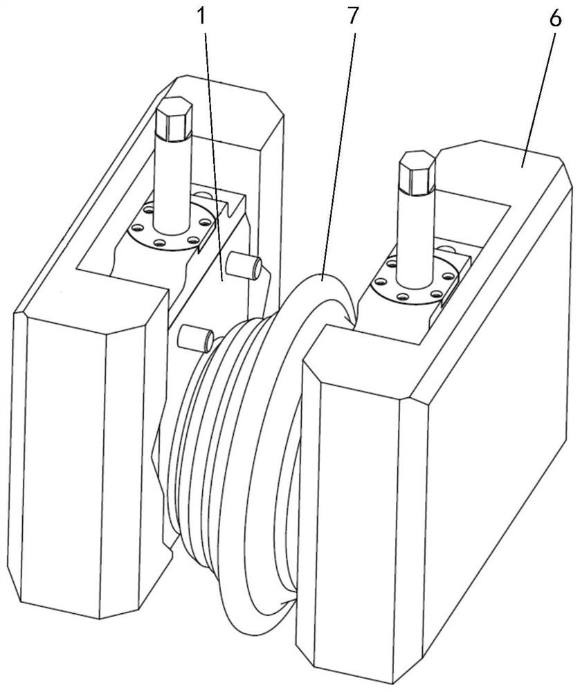
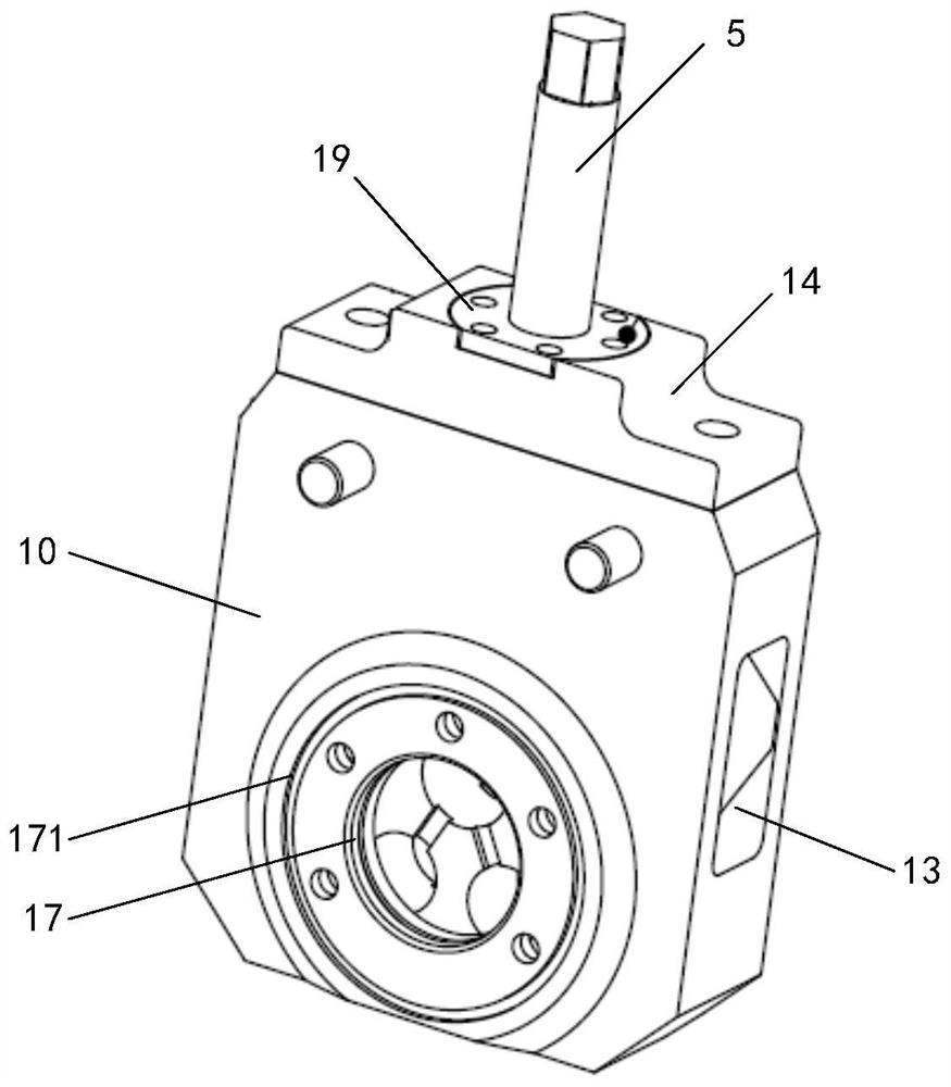
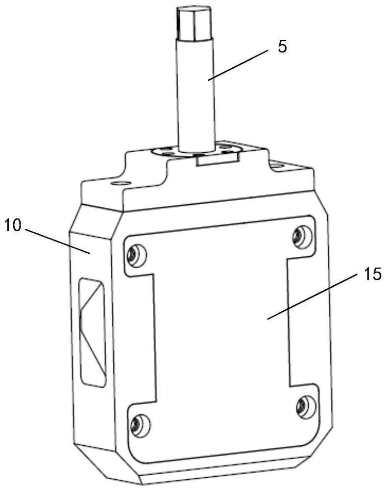
[0051] Please refer to Figure 1 to Figure 15 , figure 1 The general assembly drawing of the tool changing device of the shield machine provided by a specific embodiment of the present invention; figure 2 for fi...


PUM


Abstract

The invention discloses a shield tunneling machine and a tool changing device thereof. The tool changing device comprises a shell with a protective cavity, the shell is fixedly connected with a tool,a first locking block, a second locking block and a conical sliding block are arranged in the protective cavity, and two wedge surfaces of the conical sliding block are slidably connected with the first locking block and the second locking block correspondingly. When the conical sliding block moves forwards, the conical sliding block pushes the first locking block and the second locking block to extend out of the two opposite sides of the protective cavity till the first locking block and the second locking block are matched with a locking groove of a tool apron, and locking is achieved. Whenthe conical sliding block moves reversely, the conical sliding block pulls the first locking block and the second locking block to retract from the two opposite sides of the protective cavity till thefirst locking block and the second locking block are separated from the locking groove, and unlocking is achieved. Due to the arrangement of the protective cavity, the first locking block, the secondlocking block and the conical sliding block can be prevented from being exposed in a severe construction environment for a long time, clamping stagnation of the first locking block, the second locking block and the conical sliding block due to corrosion is avoided, impurities such as muck can also be effectively prevented from penetrating into the protective cavity, clamping stagnation is avoided, the failure rate is decreased, and reliability is high.

Description

technical field [0001] The invention relates to the technical field of tunneling equipment, in particular to a shield machine and a tool changing device thereof. Background technique [0002] Shield machines are widely used in tunnel projects such as municipal infrastructure, water diversion, and road traffic. With the rapid development of urban infrastructure and supporting infrastructure projects for people's livelihood, higher requirements are put forward for the efficiency and safety of shield machines. The shield machine uses knives to cut the soil, and the knives are easy to wear, which seriously weakens the cutting ability of the knives. In order to avoid affecting the progress of the excavation, the knives need to be replaced frequently. However, the construction environment of the shield machine is harsh and the working space is limited. inevitable. [0003] Although some existing tool change devices can realize automatic tool change, most of these tool change devi...

Claims


Application Information

Patent Timeline
Patent Type & Authority Applications(China)
IPC IPC(8): E21D9/08
CPCE21D9/08
Inventor 刘飞香彭正阳刘龙暨智勇阳旭任勇肖京
Owner CHINA RAILWAY CONSTR HEAVY IND
Why Eureka
Try Eureka