
Electronic torque tool with multiplier automatic compensation device and its operating method

A torque tool and automatic compensation technology, applied in the field of torque tools, can solve problems such as error-prone, inconvenient, screw or thread collapse

Active Publication Date: 2015-11-11
ECLAT TORQ TECH
View PDF8 Cites 0 Cited by
  • Summary
  • Abstract
  • Description
  • Claims
  • Application Information

AI Technical Summary

Problems solved by technology

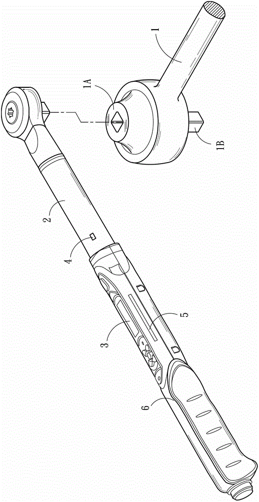
[0004] However, in the prior art, the torque data displayed by the display element 3 is only the output torque of the torque tool 6, not the real torque of the locking screw. The real actual locking torque must be multiplied by the used torque. The magnification of the force multiplier 1 is the actual locking torque output through the force multiplier 1, so the operator must continue to calculate manually to operate accurately, which is inconvenient and error-prone. Therefore, once the operator records Wrong magnification of the force multiplier 1, or wrong calculation, will often cause the screw or thread to collapse, resulting in extremely heavy losses
[0005] Obviously, this kind of existing operation method is quite inconvenient to use, and the operator needs to convert the operating torque by himself before using it correctly, and when the operator uses the force multiplier 1 with different magnifications, it is also difficult to use it in a short period of time. Correctly calculate the actual output torque output through the force multiplier 1 according to the magnification of the force multiplier 1, and the operator also has the risk of calculation errors, which are all caused by the difference between the displayed torque and the actual output torque value. Therefore, the operator cannot immediately know the state of the locking screw, which is extremely inconvenient and extremely dangerous

Method used


Image

  • Electronic torque tool with multiplier automatic compensation device and its operating method
  • Electronic torque tool with multiplier automatic compensation device and its operating method
  • Electronic torque tool with multiplier automatic compensation device and its operating method

Examples


Embodiment Construction

[0020] The detailed content and technical description of the present invention are now further described with examples, but it should be understood that these examples are for illustrative purposes only and should not be construed as limitations on the implementation of the present invention.

[0021] see image 3 As shown, the present invention is an electronic torque tool with a force multiplier automatic compensation device, which includes at least one replaceable force multiplier 200, an electronic torque tool 100 with a replaceable force multiplier 200, a torque The override setting module 310 , a torque override compensation conversion module 320 and a torque operating range conversion module 330 .

[0022] The electronic torque tool 100 further includes a housing 110 , a torsion bar 120 , a torque detection element 130 , a control system 140 , a display element 150 , and a setting element 160 . Wherein the housing 110 has a grip 111 for gripping, one end of the torsion...


PUM


Abstract

The invention relates to an electronic type torsion tool with a booster automatic compensation device and an operating method of the electronic type torsion tool. The electronic type torsion tool comprises an electronic type torsion tool body, a plurality of boosters with different multiplying power, a torsion multiplying power setting module, a torsion multiplying power compensation and conversion module and a torsion operating range conversion module, wherein the electronic type torsion tool body allows the boosters to be replaced. When a different booster is replaced, automatic compensation can be achieved after the multiplying power of the booster is set, so that a torsion value displayed through the electronic type torsion tool body is equal to the torsion value output actually by the booster in real time, moreover, the operable torsion range of the electronic type torsion tool body can be updated, and serious faults caused by manual miscalculation can be avoided.

Description

technical field [0001] The invention relates to a torsion tool, in particular to a torsion tool that automatically compensates torsion and its operating method. Background technique [0002] see figure 1 and figure 2 As shown, the existing torque tool 6 has a torsion bar 2, a display element 3, a torque detection element 4 and a control system 5, which can be combined with a force multiplier 1 during work, and the force multiplier 1 can be used to enlarge For the output torque, take the multiplier 1 of five times as an example, which means that the torque multiplier input torque 1 at the input terminal 1A can amplify the torque at the output terminal 1B by 5 times and output it. [0003] And when the force multiplier 1 is used to lock the screw head (not shown), the torque detection element 4 arranged on the torsion bar 2 can be used to detect the current deformation of the torsion bar 2, and the control system can 5 Calculate the output torque relative to the deformatio...

Claims


Application Information

Patent Timeline
Patent Type & Authority Patents(China)
IPC IPC(8): B25B23/00B25B23/142
CPCB25B23/1425
Inventor 李明华
Owner ECLAT TORQ TECH
Learn More