Wheel weight assembly

一种车轮、组件的技术,应用在农用拖拉机或类似车辆的配重组件领域

Active Publication Date: 2014-01-15
DEERE & CO
View PDF12 Cites 7 Cited by
  • Summary
  • Abstract
  • Description
  • Claims
  • Application Information

AI Technical Summary

Problems solved by technology

Such assembly should not interfere with the attachment or removal of the wheels

Method used


Image

  • Wheel weight assembly
  • Wheel weight assembly
  • Wheel weight assembly

Examples


Embodiment Construction

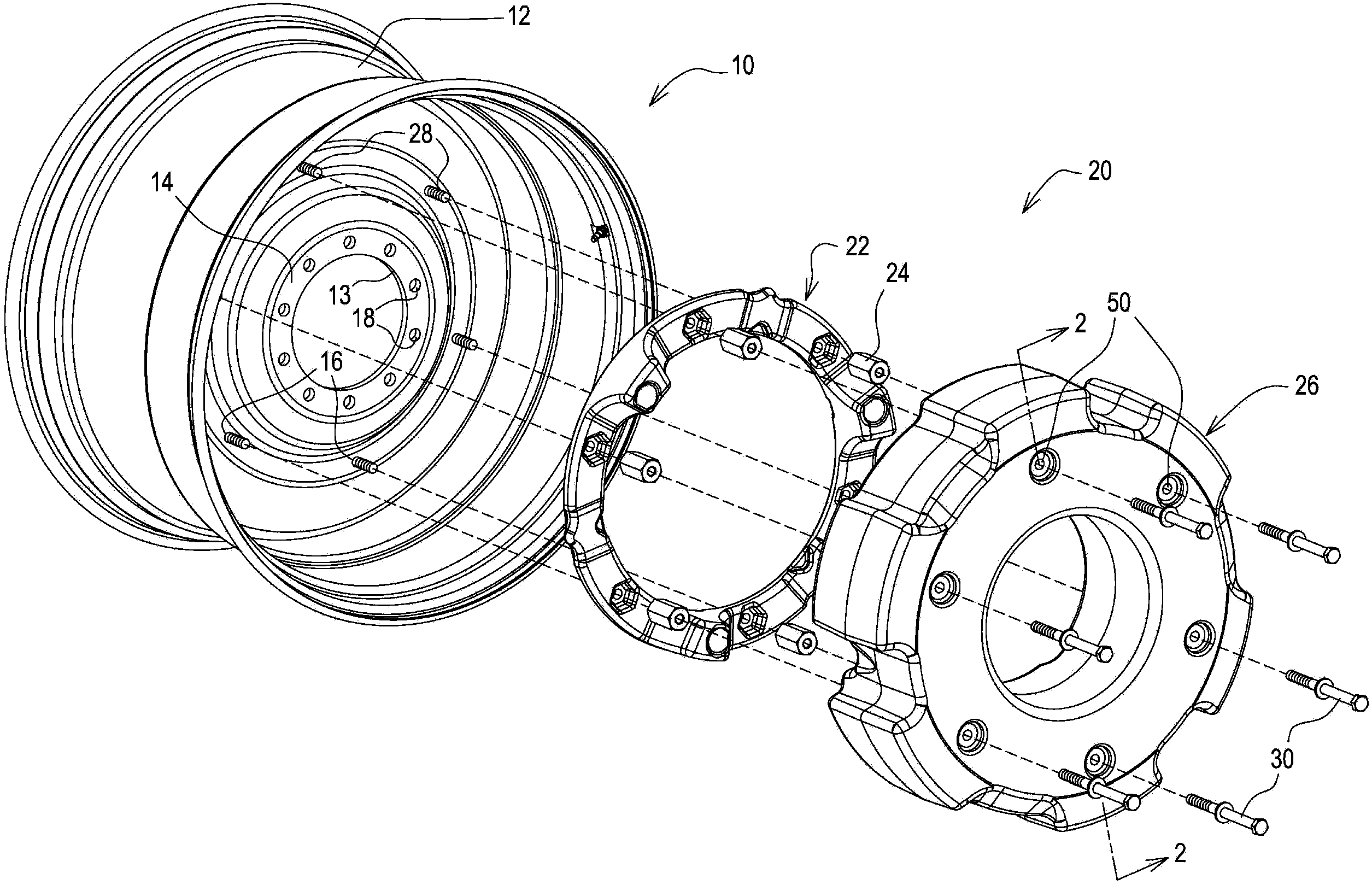
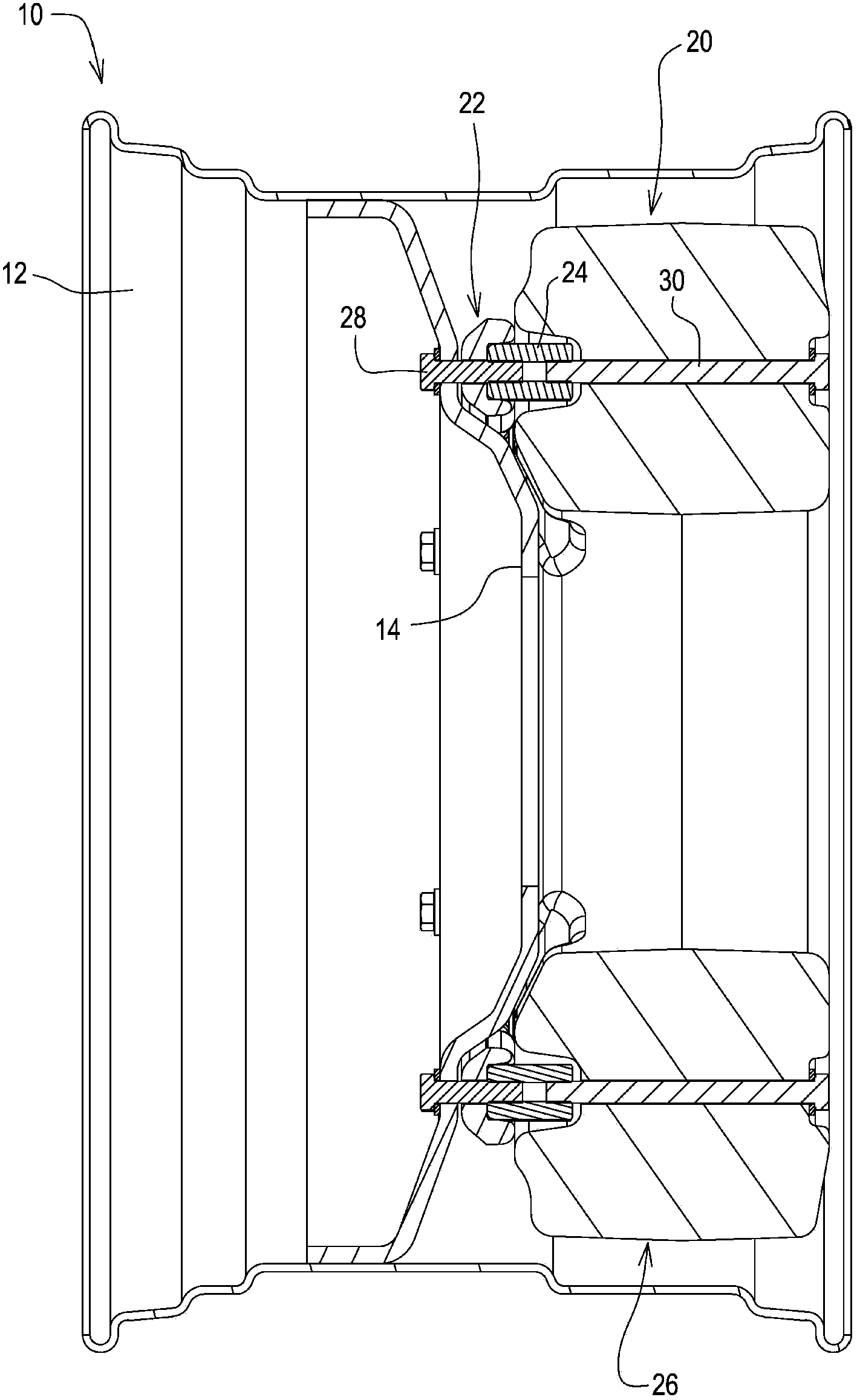
[0012] refer to figure 1 with figure 2 , the vehicle wheel 10 includes a rim 12 and a central disc portion 14 . A pneumatic tire (not shown) is mounted on the rim 12 as is well known in the art. The central disc portion 14 includes a central hole 13 , an inner set of hub mounting holes 18 and an outer set of counterweight mounting holes 16 . The wheel weight assembly 20 includes an annular inner or primary weight 22 , a set of nut members 24 , an outer weight 26 , a set of inner bolts 28 and a set of outer bolts 30 .

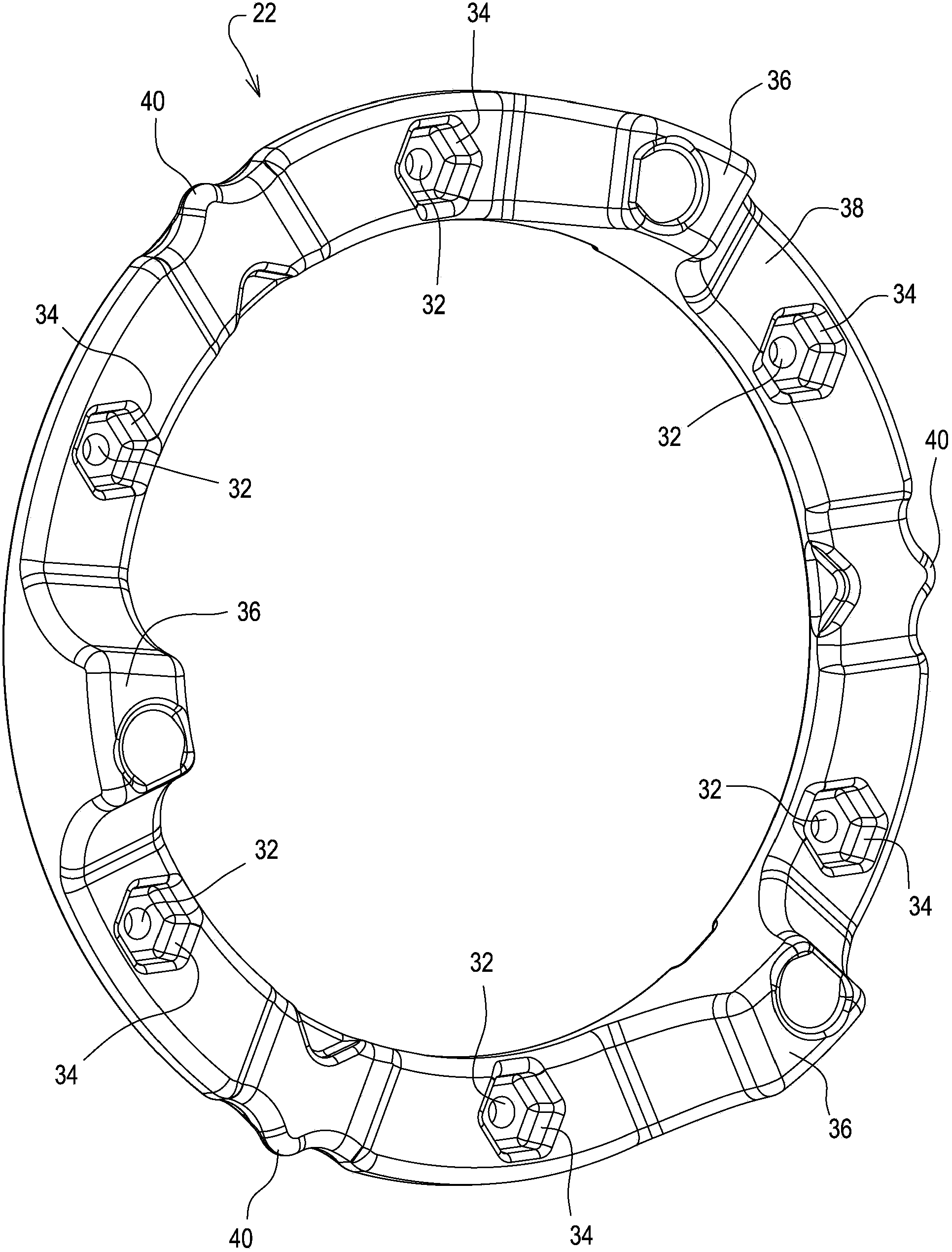
[0013] see now figure 1 , 2, 3 and 4, the initial counterweight 22 is annular, and is mounted to be in contact with the wheel disc portion 14 . The initial weight 22 has a plurality of mounting holes 32 extending axially therethrough. The hole 32 is aligned with the hole 16 of the wheel disc 14 . Surrounding each hole 32 is a recess or recess 34 of polygonal shape, preferably hexagonal or hexahedral, opening axially outwards. A plurality of spaced apart ...


PUM


Abstract

A wheel weight assembly for use on a vehicle wheel having a wheel disk section, the wheel weight assembly comprising: an annular starter weight mounted to the wheel disk section, the starter weight having a plurality of mounting bores extending axially therethrough; a plurality of nut members; a plurality of threaded members for attaching the starter weight to the wheel disk section, each threaded member extending through a corresponding one of the mounting bores and into a corresponding one of the nut members; an annular outer weight having a plurality of attaching bores aligned with the bores of the starter weight extending axially therethrough; and a plurality of attaching bolts, each attaching bolt extending through a corresponding one of the attaching bores and being threadably received by a corresponding one of the nut members, wherein the nut members are positioned between the starter weight and the outer weight.

Description

technical field [0001] The present invention relates to wheel weight assemblies and, in particular, to a weight assembly for an agricultural tractor or similar vehicle. Background technique [0002] Wheel weight assemblies are used on farm tractors or similar vehicles. Installation of some such wheel weight assemblies is time consuming and difficult. Some such assemblies include long bolts. These bolts must be inserted through the holes in the wheel from the inside so that the bolt shanks extending outward from the edge sag downwards by gravity. Sliding the holes in the counterweight over the bolts is very difficult because the heavy counterweight must be lifted and held in place while the holes line up with the bolts. [0003] Another commercially available wheel weight assembly includes one or two weights attached to the wheel using stud type bolts that pass through the wheel and then protrude through the weights. Successive counterweights are bolted to previous counte...

Claims


Application Information

Patent Timeline
Patent Type & Authority Applications(China)
IPC IPC(8): B60B15/28
CPCB60B2900/112B60B2310/305B60B2320/10B60B2900/531B60B2360/147B60B2900/3314B60B2900/115B60B15/28B60Y2200/221
Inventor 乔纳森·T·罗斯大卫·J·伊斯顿罗纳德·A·马丁蒂莫西·W·彼德曼
Owner DEERE & CO
Why Eureka
Try Eureka