
Engage the shift fork of the shifting mechanism

A switching mechanism and shift fork technology, which is applied to clutches, mechanical equipment, mechanical drive clutches, etc., can solve the problems of sheet shedding, prevent peeling or cracks, reduce processing hours, and reduce costs

Active Publication Date: 2016-05-11
HONDA MOTOR CO LTD
View PDF7 Cites 0 Cited by
  • Summary
  • Abstract
  • Description
  • Claims
  • Application Information

AI Technical Summary

Problems solved by technology

At this time, in the techniques described in the above-mentioned Patent Documents 1 and 2, the groove-shaped notch portion or the locking portion is formed so as to reach the axial side surface of the shift fork portion, and thus there is a possibility that the groove-shaped notch portion or the locking portion reaches the axial side surface of the fork portion. Stress concentration occurs in the resin in contact with the part or the locking part and breaks, so that the sheet falls off from the fork part

Method used


Image

  • Engage the shift fork of the shifting mechanism
  • Engage the shift fork of the shifting mechanism
  • Engage the shift fork of the shifting mechanism

Examples


no. 1 Embodiment approach

[0038] Below, based on Figure 1 ~ Figure 4 A first embodiment of the present invention will be described.

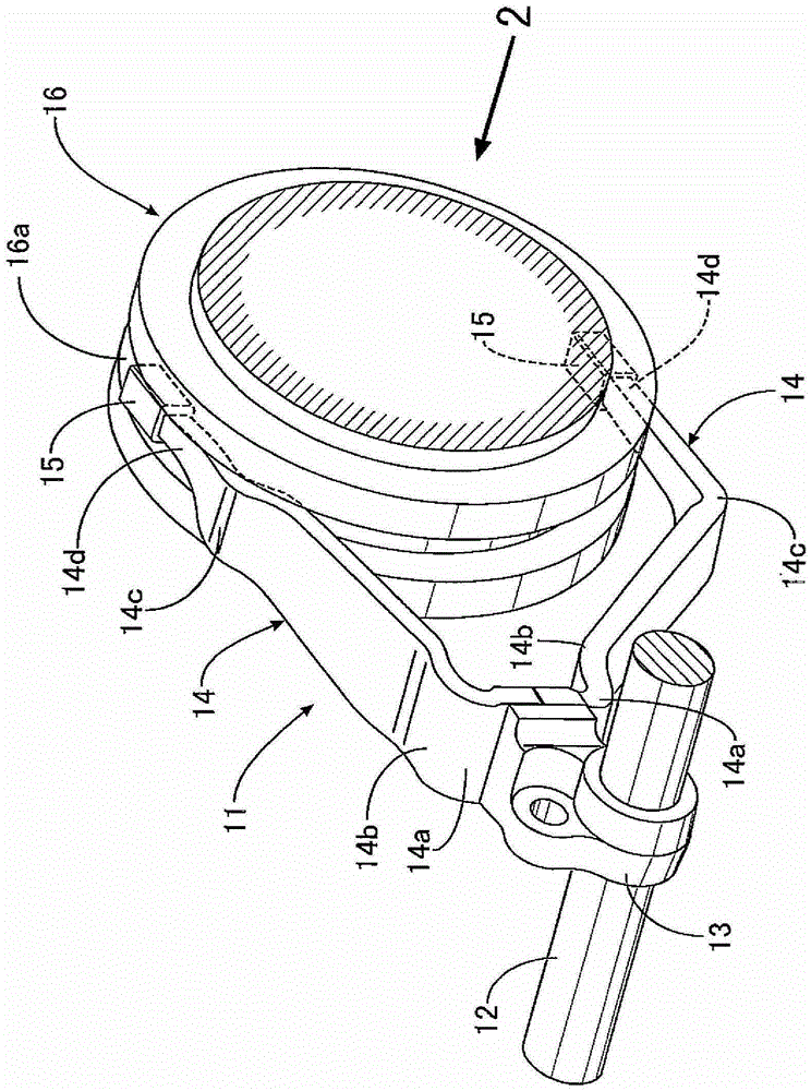
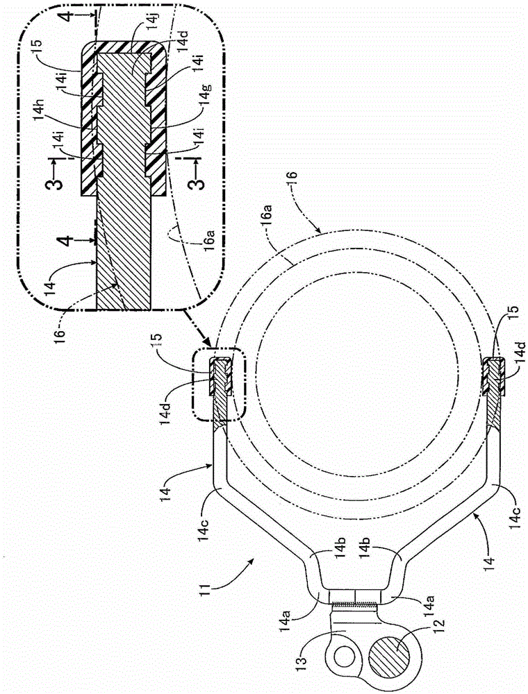
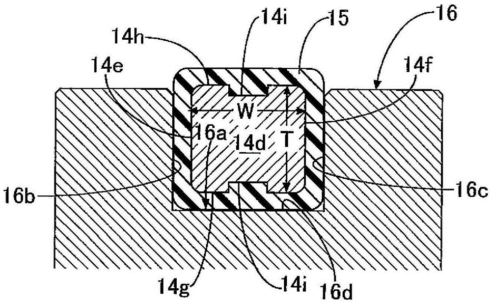
[0039] Such as figure 1 and figure 2 As shown, the shift fork 11 that operates the synchronous device of the motor vehicle transmission includes: a bushing portion 13 that is fixed to the shift fork shaft 12, and the shift fork shaft 12 is connected to the shift lever or the actuator operated by the driver. and a pair of shift fork parts 14, 14 branched from the sleeve part 13 in a double-fork shape. Each shift fork portion 14 is manufactured by punching a metal plate of a fixed thickness into a predetermined shape by shearing and punching, and then bending the first to third bending portions 14a, 14b, and 14c in the thickness direction. It is joined to the boss portion 13 by welding. A wear-resistant resin thin piece 15 is provided at a distal end portion 14d of the shift fork portion 14, and the thin piece 15 is fitted in an annular fork groove 16a formed on an o...

no. 2 Embodiment approach

[0054] Next, based on Figure 5 A second embodiment of the present invention will be described.

[0055] In the first embodiment, the width W of the distal end portion 14d of the shift fork portion 14 is constant, but in the second embodiment, the width W increases toward the distal end side of the distal end portion 14d. As a result, even if the load to remove the sheet 15 from the terminal portion 14d increases, the sheet 15 is less likely to fall off, thereby further improving durability.


PUM


Abstract

The invention provides a shifting fork of an engagement switching mechanism, which can reliably prevent a thin sheet disposed at the tail end of the fork part of the shifting fork from getting disengaged with a simple structure. A recess (14i) isolated from axial side faces (14e, 14f) is formed in an radial inner surface (14g) and a radial outer surface (14h) of a tail end (14d) of the fork part (14), and the thin sheet (15) made of resin is injection molded and covers the recess. Therefore, the resin flows into the recess and plays a role as an anchor bolt, thereby preventing the thin sheet from getting disengaged from the tail end of the fork part. Further, since the recess is disposed in the radial inner surface and the radial outer surface of the fork part, the recess is isolated from the axial side faces which mainly bear loads of strong force of inner side faces (16b, 16c) of a cylinder (16). As aresult, the resin in contact with the recess is prevented from getting broken due to stress concentration, and the thin sheet is further reliably prevented from getting disengaged from the tail end of the fork part.

Description

technical field [0001] The present invention relates to a shift fork in which an engagement switching mechanism of a thin resin sheet fitted into a fork groove of a sleeve is provided at a distal end of a fork portion. Background technique [0002] According to the following patent documents 1 and 2, the following technology is known: the tip of the fork portion of the shift fork is covered with a thin sheet made of resin excellent in wear resistance, the thin sheet is fitted into the fork groove of the sleeve, and Moving in the axial direction, the shift fork is used to drive a sleeve of a synchronizer or the like of a motor vehicle transmission to establish a desired gear. [0003] In these conventionally known shift forks, in order to prevent the thin piece made of resin from falling off from the distal end of the shift fork, the resin of the thin sheet flows into the groove-shaped notch or catch formed at the distal end of the shift fork. Fixed part, to make the sheet f...

Claims


Application Information

Patent Timeline
Patent Type & Authority Patents(China)
IPC IPC(8): F16D23/14
Inventor 小西弘顺酒井宏大里井雄飞秋山和德
Owner HONDA MOTOR CO LTD
Learn More