Brake generator

A technology for generators and braking mechanisms, which is applied to motors, electromechanical devices, electric vehicles, etc. It can solve the problems of high heat generation and inability to work for a long time, and achieve the effect of stably controlling the speed of the vehicle

Inactive Publication Date: 2014-01-15
GUIZHOU HUAKE ALUMINUM MATERIAL ENG TECH RES
View PDF0 Cites 4 Cited by
  • Summary
  • Abstract
  • Description
  • Claims
  • Application Information

AI Technical Summary

Problems solved by technology

[0004] The technical problem to be solved by the present invention is: aiming at the problems that the brake pads cannot work for a long

Method used


Image

  • Brake generator

Examples


Example Embodiment

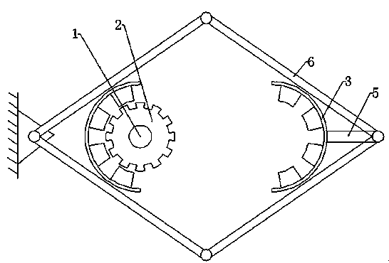
[0015] Embodiment 1; as figure 1 , the rotor 2 is installed on the vehicle axle 1, a semicircular stator 3 is fixedly installed on the left side of the rotor 2, and the other semicircular stator 3 is installed on the right side of the rotor 2 through a telescopic mechanism 5, which is hinged by four connecting rods 6. , the hinge point at the left end is fixed on the left side of the left semicircular stator 3 , and the semicircular stator 3 is installed on the hinge point on the right through the support rod 5 . There are permanent magnet poles on the semicircular stator 3, and a coil is wound on the rotor 2, and the coil is connected to a switching power supply. The switching power supply can adjust the output voltage of the coil to output a stable value. Automobile brakes are divided into two-stage brakes. The first-stage brakes control the distance between the semicircular stator 3 and the rotor 2, and the second-stage brakes are consistent with the existing brake pads. ...

Example Embodiment

[0017] Example 2:

[0018] The rotor 2 is installed on the vehicle axle 1, a semicircular stator 3 is fixedly installed on the left side of the rotor 2, and the other semicircular stator 3 is installed on the right side of the rotor 2 through a telescopic mechanism 5, which is hinged by four connecting rods 6. The hinge point at the left end is fixed on the left side of the left semicircular stator 3 , and the semicircular stator 3 is installed on the right hinge point through the support rod 5 . There are permanent magnet poles on the rotor 2, a coil is wound on the semicircular stator 3, the coil is connected with a switching power supply, and the switching power supply can adjust the output voltage of the coil to output at a stable value. Automobile brakes are divided into two-stage brakes. The first-stage brakes control the distance between the semicircular stator 3 and the rotor 2, and the second-stage brakes are consistent with the existing brake pads.

[0019] Working ...


PUM


Abstract

The invention discloses an automobile brake generator. The automobile brake generator comprises a rotor (2) and a stator. The rotor (2) is mounted on an automobile axle (1). The stator is composed of two semicircular stators (3), wherein one semicircular stator (3) is mounted on one side of the rotor (2) through a telescoping mechanism (5), the telescoping mechanism (5) is connected with a brake mechanism of an automobile, and the other semicircular stator (3) is fixed on the other side of the rotor (2). According to the automobile brake generator, rotation of the axle is used for generating electricity, mechanical energy needing to be wasted originally of the automobile is converted into electric energy to be used, and meanwhile corresponding reactive force is generated so that the speed of the automobile can be controlled.

Description

technical field [0001] The invention relates to a generator. Background technique [0002] The current car brakes use friction to control the speed of the car. The advantage of using this method is that it can respond quickly and slow down in time. However, because it converts kinetic energy into heat energy, it cannot be used for a long time, and it will fail due to overheating. When encountering a downhill section, especially in the southwestern region, there are a large number of long downhill sections. When the vehicle is driving on this section, the load on the brakes is very large. When going downhill, the resistance of the brake pads is greater than usual, so it is easy to It is damaged, easy to carbonize, and has relatively large wear and tear. When the brake pads age, it is easy to wear off all the carbon tiles on the brake pads, leaving only the friction between iron and iron, resulting in brake failure. In addition, due to long-term downhill braking, the temper...

Claims


Application Information

Patent Timeline
IPC IPC(8): H02K7/00B60L7/10
CPCY02T10/64
Inventor 张中可
Owner GUIZHOU HUAKE ALUMINUM MATERIAL ENG TECH RES
Why Eureka
Try Eureka