Method and apparatus for carrier synchronization
A carrier synchronization and carrier technology, applied in the field of communication, can solve problems such as low resource utilization, and achieve the effect of improving resource utilization
- Summary
- Abstract
- Description
- Claims
- Application Information
AI Technical Summary
Problems solved by technology
Method used
Image

Examples
Embodiment 1
[0093] This preferred embodiment provides three methods for distinguishing new carrier types, so that the UE can distinguish whether the new carrier is a synchronous or asynchronous carrier, and receives a synchronization signal on the non-synchronized carrier to complete the carrier synchronization process.
[0094] The method in this preferred embodiment comprises the steps: Figure 9 It is the process of carrier synchronization according to the preferred embodiment of the present invention Figure 1 ,Such as Figure 9 As shown, the method includes step S902 and step S904.
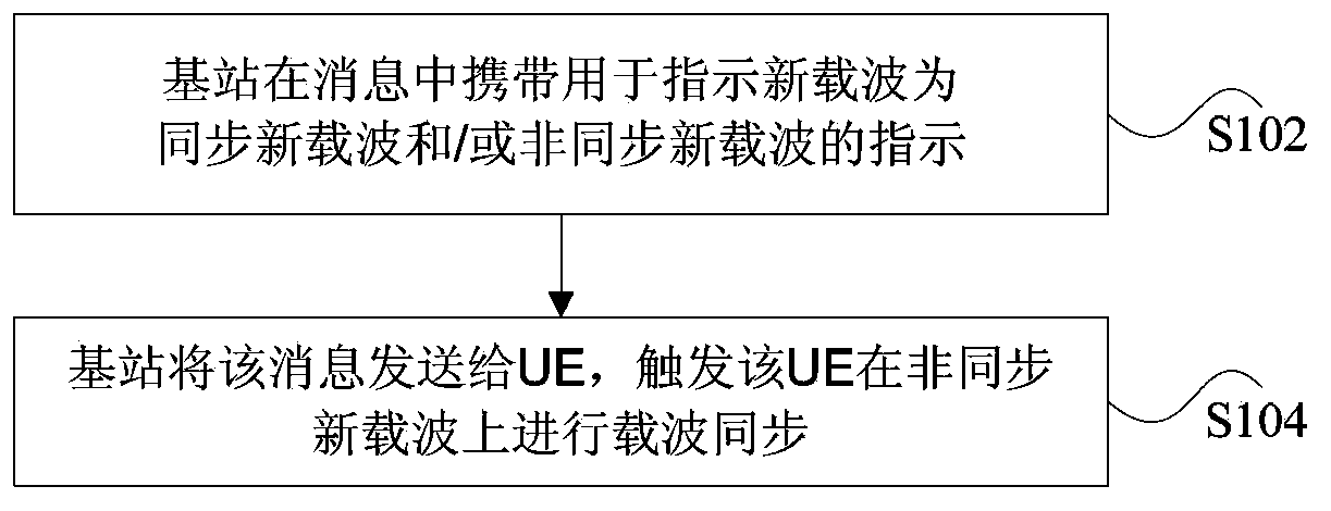
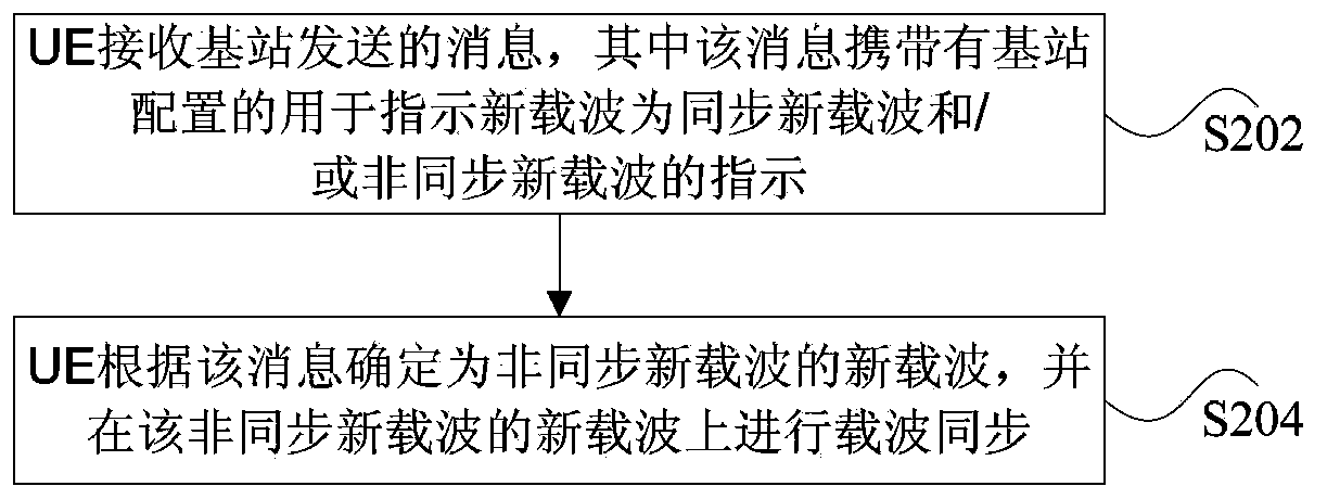
[0095] Step S902: the base station instructs the UE that the new carrier is a synchronous or asynchronous new carrier.
[0096] Step S904: The UE receives the synchronization signal on the new non-synchronized carrier according to the instruction of the base station to complete the synchronization of the new carrier.
[0097] The above steps can be realized through the following three methods.
[009...
Embodiment 2
[0110] This preferred embodiment provides a method for carrier synchronization. In this preferred embodiment, it distinguishes whether the configured new carrier is a synchronous new carrier or a non-synchronized new carrier according to a predetermined rule, so that after the UE is configured with a new carrier, it can The corresponding indication determines whether it is necessary to receive synchronization information to complete the synchronization of the new carrier.
[0111] The frequency division duplex mode (Frequency Division Duplex, FDD for short) is taken as an example for description below.
[0112] Such as Figure 8 As shown, carrier 1 (downlink frequency point f1, uplink frequency point f1'), referred to as CC1 (DL f1, UL f1'), the serving cell is a compatible cell; carrier 2 (downlink frequency point f2), referred to as CC2 ( DLf2) is a new carrier; carrier 3 (downlink frequency point f3), referred to as CC3 (DLf3); user equipment UE camps on CC1 and initiates ...
example 1
[0114] Example 1: Corresponding to the first method of the above-mentioned preferred embodiment, the method includes the following steps S302 to S310.
[0115] Step S302: the UE initiates an RRC connection on CC1, and completes the UE's access in CC1.
[0116] Step S304: The base station sends an RRC connection reconfiguration message to the UE on CC1, the message carries configuration information of CC2 and CC3, and carries information indicating the carrier types of CC2 and CC3, that is, the configuration of CC2 carries information indicating that CC2 is a new carrier for synchronization Marker bit information, the configuration of CC3 carries the flag bit information indicating that CC3 is an asynchronous new carrier.
[0117] Step S306: After receiving the RRC message, the UE applies configurations to CC2 and CC3 respectively, and starts a synchronization process of CC3 on CC3.
[0118] Step S308: After a period of time, the base station sends an RRC connection reconfigur...
PUM
 Abstract
Description
Claims
Application Information
 - R&D
- Intellectual Property
- Life Sciences
- Materials
- Tech Scout
- Unparalleled Data Quality
- Higher Quality Content
- 60% Fewer Hallucinations
Browse by: Latest US Patents, China's latest patents, Technical Efficacy Thesaurus, Application Domain, Technology Topic, Popular Technical Reports.
© 2025 PatSnap. All rights reserved.Legal|Privacy policy|Modern Slavery Act Transparency Statement|Sitemap|About US| Contact US: help@patsnap.com