Drawer guide rail structure

A guide rail and drawer technology, applied in drawers, furniture parts, household appliances, etc., can solve the problems of poor guide rail performance, increased gap between balls and rails, and insufficient strength, so as to improve rigidity, smooth guide rail operation, and increase load bearing effect of ability

Inactive Publication Date: 2014-01-22
李绍汉
View PDF6 Cites 1 Cited by
  • Summary
  • Abstract
  • Description
  • Claims
  • Application Information

AI Technical Summary

Problems solved by technology

[0005] However, in the actual application process, it was found that the performance of the guide rail of some products deteriorated when the load intensity of the drawer was relatively high. The deformation of the ball causes the gap between the ball and the track to increase

Method used


Image

  • Drawer guide rail structure
  • Drawer guide rail structure
  • Drawer guide rail structure

Examples


Embodiment Construction

[0023] Further illustrate the present invention below in conjunction with accompanying drawing and embodiment.

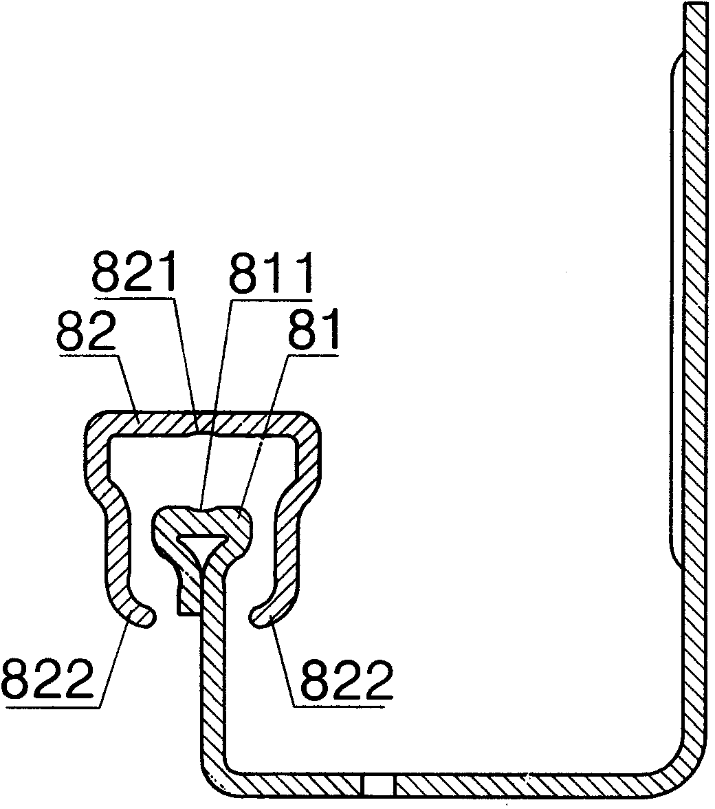
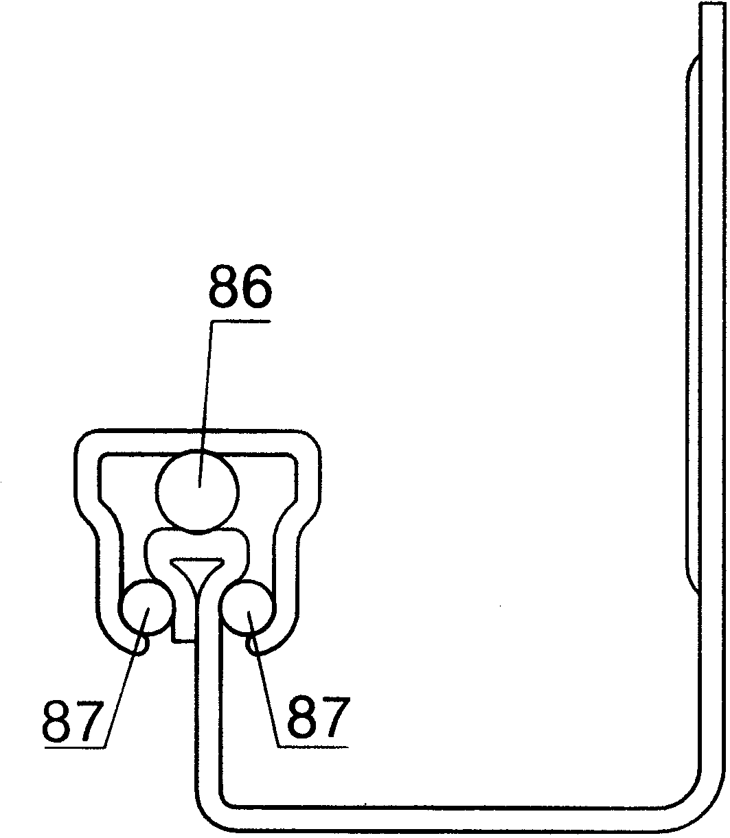
[0024] figure 1 and figure 2 It is a structure of existing guide rail products, which includes a fixed rail 81 and a movable rail 82 surrounded by the fixed rail 81. The loading part of the fixed rail 81 has an inverted triangular cross-section, and the surface of the movable rail 82 is roughly П-shaped; The upper surface of the horizontal edge has a first raceway 811; the lower surface of the horizontal edge of the movable rail 82 has a second raceway 821, and a first ball 86 is embedded between the first raceway 811 and the second raceway 821; the movable rail 81 The lower ends of the two vertical sides have a first bending portion 822; the two first bending portions 822 of the movable rail 82 are opposite to the two triangular hypotenuses of the fixed rail 81, and each first bending portion 822 is connected to the fixed rail. The second ball 87 is embedded res...


PUM


Abstract

The invention belongs to hardware products, and relates to a drawer guide rail structure. The drawer guide rail structure comprises a fixed rail, a middle rail and a movable rail, and a first rolling way is arranged on the horizontal side of the bearing portion of the fixed rail. A second rolling way is arranged on the horizontal side of the middle rail, and a first ball is arranged between the first rolling way and the second rolling way. A rolling column is arranged between the lower surface of the horizontal side of the movable rail and the upper surface of the horizontal side of the middle rail. First bent portions are arranged at the lower ends of the two vertical sides of the movable rail. The two downward sides at the two ends of the horizontal side of the middle rail are respectively provided with a second bent portion, a third bent portion and a fourth bent portion from top to bottom in sequence, and second balls are embedded between the second bent portions and the first bent portions. Third balls are embedded between the third bent portions and the triangular inclined sides of the fixed rail, and the fourth bent portions start to be bent from the tail ends of the third bent portions and extend towards to the outer sides of the downward sides of the middle rail. The drawer guide rail structure increases the bearing capacity of the middle rail, a guide rail is made to operate more smoothly, the overall deflection of a drawing cabinet is reduced, and the drawer guide rail structure is suitable for being arranged on furniture for use.

Description

technical field [0001] The invention relates to hardware products, in particular to a furniture guide rail. Background technique [0002] Common drawer guide rails are composed of fixed rails and movable rails. In order to improve the bearing capacity and smoothness of the guide rails, manufacturers continue to improve the guide rail structure. [0003] The invention patent named "drawer rail structure" (application date 2012-04-01, application number 2012100952763) discloses a drawer rail, which includes a fixed rail and a movable rail surrounded by the fixed rail. The bearing part of the fixed rail has Inverted triangular cross-section, the cross-section of the movable rail is roughly П-shaped, and there is a cage between the fixed rail and the movable rail; the upper surface of the horizontal side of the fixed rail bearing part has a concave first raceway; the lower surface of the horizontal side of the movable rail is also concave The second raceway, the first ball is e...

Claims


Application Information

Patent Timeline
Patent Type & Authority Applications(China)
IPC IPC(8): A47B88/04
Inventor 李绍汉
Owner 李绍汉
Why Eureka
Try Eureka