Tool for butt joint assembly of front transmission casing of engine and rear transmission casing of engine

A transmission casing and rear transmission technology, which is applied in the direction of metal processing, manufacturing tools, workpiece clamping devices, etc., can solve the problems of low stability and reliability, prone to accidents, cumbersome operation, etc., and achieve convenient transportation and turnover. Effects of improving safety and reducing workload

Active Publication Date: 2014-01-22
CHENGDU ENGINE GROUP
View PDF7 Cites 17 Cited by
  • Summary
  • Abstract
  • Description
  • Claims
  • Application Information

AI Technical Summary

Problems solved by technology

[0003] Regarding the butt joint assembly of the front transmission casing and the rear transmission casing, the existing technology is to directly assemble the front transmission casing and the rear transmission casing on the engine through the installation hole positions. During assembly, the operator turns the engine over and then steps on the engine. For hoisting, first assemble the rear transmission casing and transmission shaft to the engine, then fix the front transmission casing to the engine, and then install the transmission shaft into the front transmission casing, so the relative positions of the front transmission casing and the rear transmission casing The stability and reliability are not high, and it is prone to deflection, and the operation is cumbersome, unsafe, and prone to accidents

Method used


Image

  • Tool for butt joint assembly of front transmission casing of engine and rear transmission casing of engine
  • Tool for butt joint assembly of front transmission casing of engine and rear transmission casing of engine
  • Tool for butt joint assembly of front transmission casing of engine and rear transmission casing of engine

Examples


Embodiment Construction

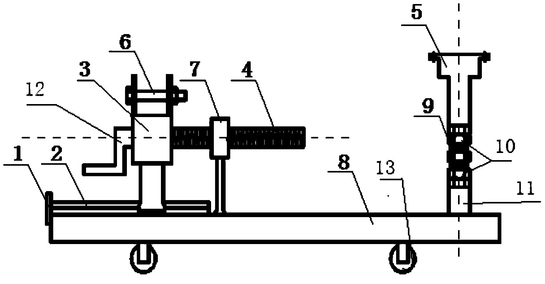
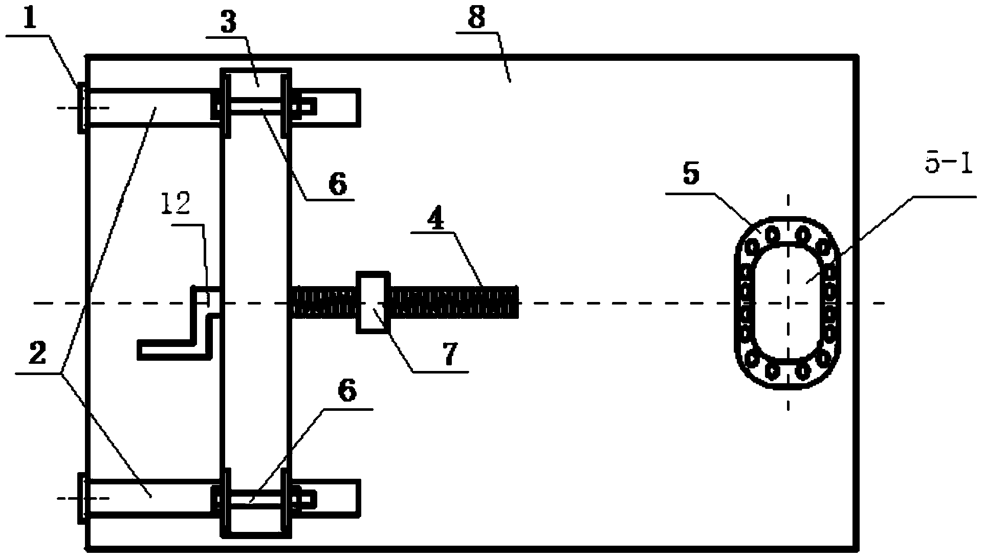
[0028] The structure of the tooling for the butt joint assembly of the engine front transmission casing and the rear transmission casing of the present invention will be further described below through the embodiments and in conjunction with the accompanying drawings.

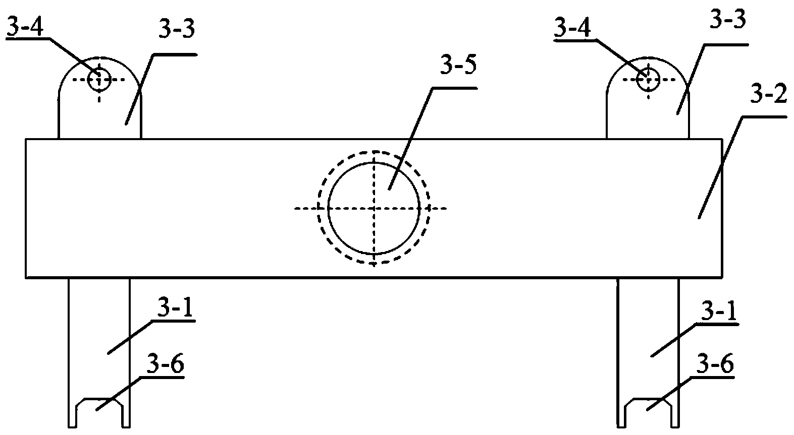
[0029] In this embodiment, the tooling for the butt joint assembly of the front transmission casing and the rear transmission casing of the engine is as follows: figure 1 , figure 2 As shown, it includes base 8, two guide rails 2, two stop blocks 1, rear transmission case holder 3, rear transmission case holder driver, front transmission case holder 5, height adjustment of front transmission case holder Stud 9, stud mount 11 and screw support body 7. Base 8 is a rectangular plate-shaped body, which is a supporting platform for all parts or components, and its bottom surface is equipped with road wheels 13; as an integrated structure (see figure 1 ); Rear transmission box fixing seat 3 such as image 3 , ...


PUM


Abstract

A tool for butt joint assembly of a front transmission casing of an engine and a rear transmission casing of the engine comprises a base, guide rails, a rear transmission casing fixing base, a front transmission casing fixing base, a rear transmission casing fixing base drive element, a front transmission casing fixing base height adjusting bolt and a bolt installation base. The rear transmission casing fixing base drive element is formed by a screw rod and a rocker. The rear transmission casing fixing base is composed of a base body, two upright columns and two supporting bases. The screw rod in the rear transmission casing fixing base drive element is arranged in a screw hole formed in the base body of the rear transmission casing fixing base, the number of the guide rails is two, the two guide rails are arranged at one end of the top face of the base in parallel, and guide grooves formed in the lower ends of the two upright columns of the rear transmission casing fixing base are combined with the two guide rails. The bolt installation base is fixedly arranged at the other end of the top face of the base, the lower end of the front transmission casing fixing base height adjusting bolt is combined with a screw hole formed in the bolt installation base, and the upper end of the front transmission casing fixing base height adjusting bolt is combined with a screw hole formed in the front transmission casing fixing base and is fastened through a fastening nut.

Description

technical field [0001] The invention belongs to the field of assembling the front transmission casing and the rear transmission casing of an aero-engine, and in particular relates to a butt joint assembly tool for the front transmission casing and the rear transmission casing. Background technique [0002] The front transmission casing is driven by the high and low pressure air compressor rotors of the engine through the bevel gear pair, and then the power is transmitted to the rear transmission casing through the transmission shaft to provide power for the transmission accessories of the engine, so that the fuel and lubricating oil systems of the engine, hydraulic pressure, etc. The system works normally. Whether the docking of the front transmission casing and the rear transmission casing is successful or not directly affects the axial runout of the front transmission casing, the rear transmission casing, the transmission shaft and the deflection position of the two casing...

Claims


Application Information

Patent Timeline
Patent Type & Authority Applications(China)
IPC IPC(8): B23P19/00B25B11/02
CPCB25B11/02B25B27/00
Inventor 刘建汤福龙李峥彭武龙王雷韩丹
Owner CHENGDU ENGINE GROUP
Why Eureka
Try Eureka