Integrated fixture of laser chip

A chip and laser technology, used in manufacturing tools, workpiece clamping devices, parts of electrical measuring instruments, etc., can solve the problems of easy blockage of vacuum holes, deviation from the initial position, increase processing difficulty, etc., and reduce the loading time. Difficulty, Guaranteed Accuracy, Ingenious Effect

Pending Publication Date: 2019-04-09
STELIGHT INSTR CO LTD
View PDF0 Cites 8 Cited by
  • Summary
  • Abstract
  • Description
  • Claims
  • Application Information

AI Technical Summary

Problems solved by technology

[0003] At present, there is a chip fixing fixture on the market, which can temporarily fix the chip through the chip groove and the vacuum hole in the chip groove. However, due to the small size of the chip used in the laser, in the actual operation process, not only The vacuum hole is easy to block, and during the placement, processing and transfer of the chip in different machines, the chip is very easy to loosen and deviate from the original position, or even bounce off the chip slot, which increases the difficulty of processing and affects its processing efficiency. , when it is necessary to perform photoelectric testing on the chip, it is necessary to add heating and testing components, which is very troublesome

Method used


Image

  • Integrated fixture of laser chip
  • Integrated fixture of laser chip
  • Integrated fixture of laser chip

Examples


Embodiment 1

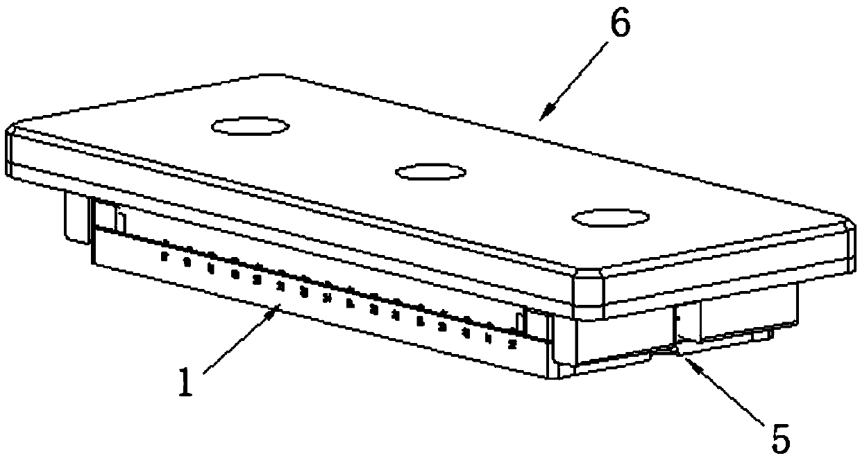
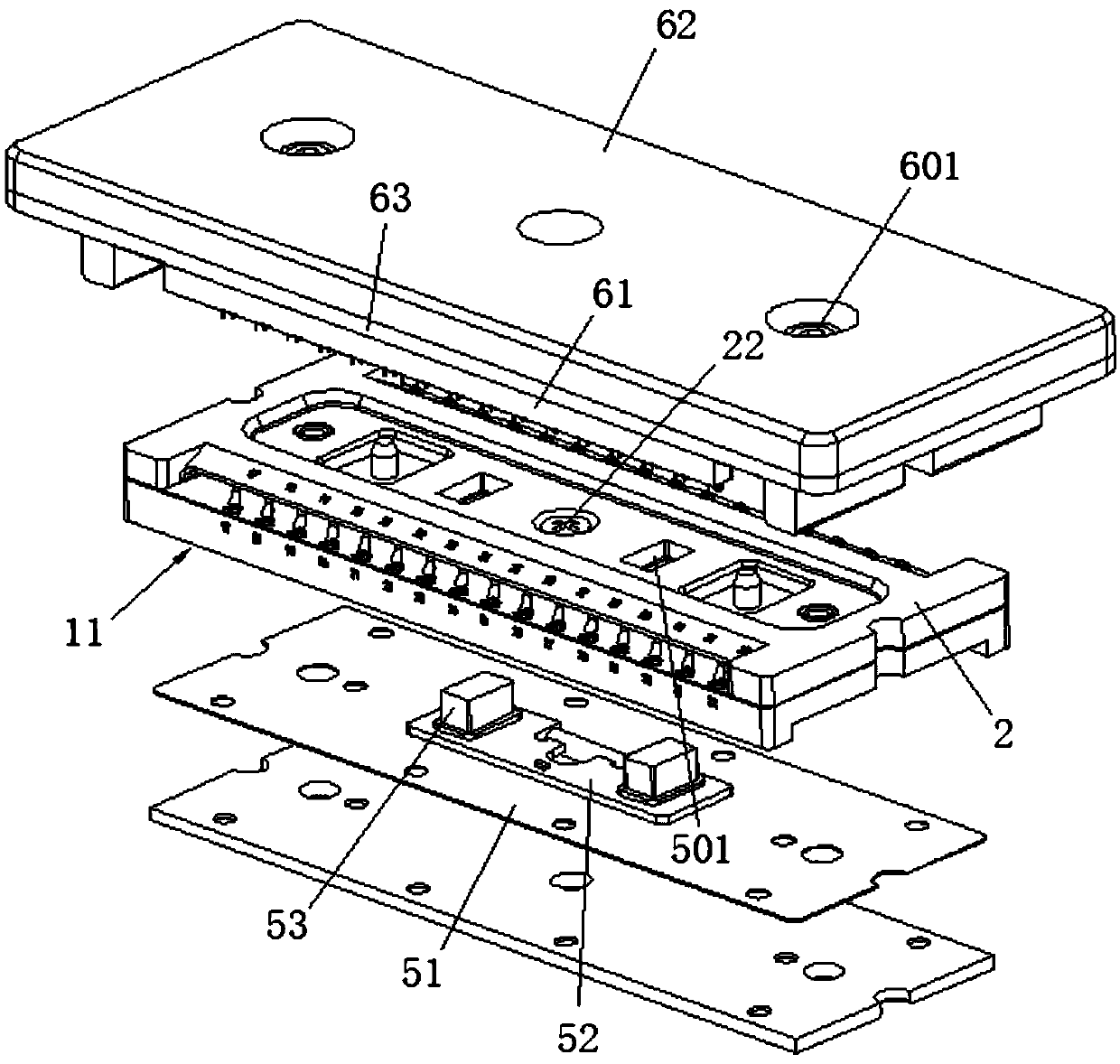
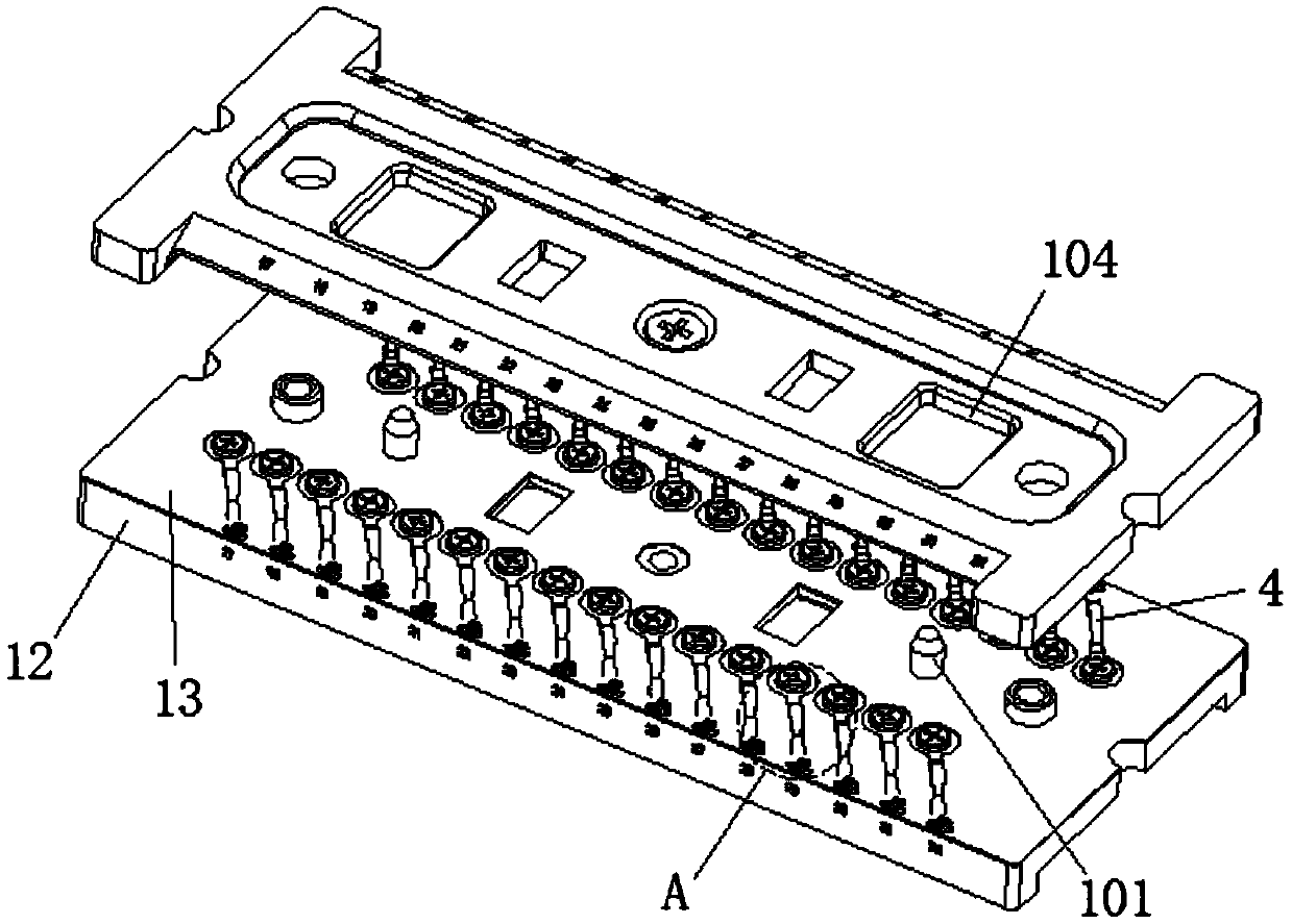
[0029] Embodiment 1: A kind of integrated fixture of laser chip, refer to attached Figure 1-6 , including a chip positioning seat 1 for loading a chip 7, a test assembly 6 and a heating assembly 5, the test assembly 6 is located above the chip positioning seat 1, the heating assembly 5 is located below the chip positioning seat 1, and the chip positioning seat 1 includes a base 11, a shrapnel 4 installed on the base 11 and a shrapnel gland 2 located above the base 11. The upper surface of the base 11 is provided with a number of positioning grooves 3 for inserting the chip 7. The shrapnel 4 includes The connecting part 41 on the 11, the deformation part 42 bent to the side of the shrapnel gland 2, and the positioning part 43 located in the positioning groove 3, the connecting part 41 and the positioning part 43 are connected by the deformation part 42, and the positioning groove 3 There is a positioning right angle 31, the end of the positioning part 43 is provided with a rig...

Embodiment 2

[0035] Embodiment 2: a kind of integrated fixture of laser chip, refer to attached Figure 1-6 , including a chip positioning seat 1 for loading a chip 7, a test assembly 6 and a heating assembly 5, the test assembly 6 is located above the chip positioning seat 1, the heating assembly 5 is located below the chip positioning seat 1, and the chip positioning seat 1 includes a base 11, a shrapnel 4 installed on the base 11, and a shrapnel gland 2 located above the base 11. The upper surface of the base 11 is provided with a number of positioning grooves 3 for inserting the chip 7. The shrapnel 4 includes The connecting part 41 on the 11, the deformation part 42 bent to the side of the shrapnel gland 2, and the positioning part 43 located in the positioning groove 3, the connecting part 41 and the positioning part 43 are connected by the deformation part 42, and the positioning groove 3 There is a positioning right angle 31, the end of the positioning part 43 is provided with a ri...


PUM


Abstract

The invention discloses an integrated fixture of a laser chip. The integrated fixture comprises a chip positioning seat for loading chips, a test module and a heat module; the chip positioning seat comprises base shrapnel and a shrapnel gland; multiple positioning slots for the embedding of the chips are formed on an upper surface of the base; the shrapnel comprises a connecting part, a deformation part and a positioning part arranged on the base; each positioning lost is provided with a positioning right angle, and a right angle positioning gap is formed at the end part of the positioning part, and the shrapnel gland and the deformation part are in extrusion contact; multiple pins corresponding to the chips are arranged at a lower surface of a PCB board, the pins contact with the chips bypenetrating a cover plate, and connecting contacts are arranged at two ends of the PCB board; the heating module comprises a heating plate and a control circuit board. The integrated fixture disclosed by the invention has the advantages of being strong in applicability and convenient for use.

Description

technical field [0001] The invention relates to an integrated fixture for a laser chip, which belongs to the technical field of chip processing. Background technique [0002] When making laser chips, not only the chip body needs to be mounted on the porcelain substrate, but also the chip body and the porcelain substrate need to be connected through gold wires, and the chip should be photoelectrically tested; therefore, in order to achieve efficient chip production, it is necessary to Chips are fixed in fixtures and processed in batches using placement and gold wire bonding equipment. [0003] At present, there is a chip fixing fixture on the market, which can temporarily fix the chip through the chip groove and the vacuum hole in the chip groove. However, due to the small size of the chip used in the laser, in the actual operation process, not only The vacuum hole is easy to block, and during the placement, processing and transfer of the chip in different machines, the chip...

Claims


Application Information

Patent Timeline
Patent Type & Authority Applications(China)
IPC IPC(8): G01R1/04B25B11/00
CPCG01R1/0425B25B11/00
Inventor 罗跃浩徐鹏嵩赵山王化发黄建军
Owner STELIGHT INSTR CO LTD
Why Eureka
Try Eureka