Workpiece auto-carry device

An automatic and carrying technology, applied in the field of manipulators, can solve the problems of low processing efficiency, offset of connecting parts, complex structure, etc., and achieve the effect of less floor space, stable and accurate force transmission process, and large working range.

Inactive Publication Date: 2014-01-22
江苏剑桥涂装工程股份有限公司
View PDF10 Cites 6 Cited by
  • Summary
  • Abstract
  • Description
  • Claims
  • Application Information

AI Technical Summary

Problems solved by technology

[0003] Chinese patent CN 101785242A discloses a manipulator, including a manipulator body, a base plate arranged on the end effector of the manipulator body, and at least two cylinders fixed on the base plate, each cylinder has a piston rod that can be stretched relative to the cylinder, and each The end of the piston rod is provided with claws, and at least two of the claws are arranged opposite to each other. When the piston rod is stretched out relative to the cylinder, the two claws are against the outer surface of the workpiece side wall to clamp the workpiece, but when the workpiece When it is hollow and needs to process different outer surfaces of the workpiece side wall, the clamping method of the above-mentioned manipulator will cover part of the outer surface of the workpiece side wall, and the clamping position of the jaws needs to be changed several times to complete the different outer surfaces of the workpiece. processing, so the processing efficiency is low
[0004] Chinese patent CN 1017858501A discloses a manipulator, including an arm, a gripper and a connecting device connecting the arm and the gripper, but since the deformed portion of the connector and the fitting hole of the holding member are interrupted close to the base, when the connection When the elastic part is compressed toward the bottom of the base, there will be a certain gap between the connecting part and the holding part, and the connecting part may be offset under the action of external force
[0005] Chinese patent CN 102785242A discloses a manipulator. The manipulator realizes the automatic holding and placement of battery slices through the cooperation of the rotating shaft, the turntable, the upper arm and the forearm. The degree of automation is high and the accuracy is good. For loading and unloading workpieces, the suction of the suction cup is not easy to control. If the suction is too small, the workpieces will not be sucked up or fall during transportation. At the same time, the structure is complex, the scope of application is small, and the cost is high

Method used


Image

  • Workpiece auto-carry device
  • Workpiece auto-carry device

Examples


Embodiment Construction

[0017] The present invention will be further described in conjunction with the accompanying drawings and embodiments.

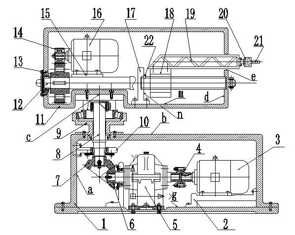
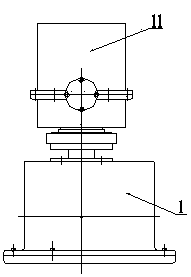
[0018] Such as Figure 1-2 As shown, the device can achieve a maximum grasping weight of 150kg, a maximum moving speed of 2m / s, an arm telescopic stroke of 200mm, a maximum working radius of 800mm, and an arm swing angle of 90°. The automatic workpiece loading device includes a box (1), one motor support plate (2), one three-phase asynchronous motor (3), flange coupling (4), reducer (5), small bevel gear (6), large bevel gear (7), Rotary shaft (8), support frame (9), support plate one (10), box body two (11), lead screw (12), large spur gear (13), small spur gear (14), motor support plate two (15), three-phase asynchronous motor two (16), support plate two (17), horizontal screw sleeve (18), truss (19), hand claw (21), cylinder (20), baffle plate (22), three The output shaft of phase asynchronous motor one (3) is connected with the input shaft of the reduce...


PUM


Abstract

A workpiece auto-carry device has two degrees of freedom including telescopic motion of a manipulator front arm and rotational motion around the vertical axis of a base. The motions are major motions of a manipulator and controlled by two motors. The motors are connected with an actuator through transmission mechanisms such as a gear so as to transmit motions. In addition, during the whole acting process, opening and closing of a claw are involved. The workpiece to be clamped is light and can be clamped at ease just with a pneumatic pump.

Description

technical field [0001] The invention relates to a manipulator, in particular to a manipulator designed for automatic delivery of processed products on the production line of an industrial production workshop, which can realize the transfer of different processing techniques of the processed parts on the production line. Background technique [0002] Industrial manipulator is an inevitable product of industrial production. It is an automatic technical equipment that imitates some functions of the upper limbs of the human body, transports workpieces or holds tools according to predetermined requirements, and plays an important role in realizing the automation of industrial production and promoting the further development of industrial production. important role. Therefore, it has a strong vitality and is widely valued and welcomed by people. Practice has proved that industrial manipulators can replace the heavy labor of human hands, significantly reduce the labor intensity of...

Claims


Application Information

Patent Timeline
Patent Type & Authority Applications(China)
IPC IPC(8): B25J9/00B25J9/10
Inventor 李映君张如剑李长春张宏高张琪张琦
Owner 江苏剑桥涂装工程股份有限公司
Why Eureka
Try Eureka