Fixed variable hydraulic system of mining dump truck

A technology for mining dump trucks and hydraulic systems, which is applied to vehicles with inclined bearing motion, fluid steering mechanisms, etc., can solve the problems of erratic steering, the stability of the steering system is not guaranteed, and the steering pump is not used. Displacement effect

Active Publication Date: 2016-04-06
GUANGXI LIUGONG MASCH CO LTD
View PDF6 Cites 0 Cited by
  • Summary
  • Abstract
  • Description
  • Claims
  • Application Information

AI Technical Summary

Problems solved by technology

[0007] (2) For the use of such as figure 2 In the hydraulic system shown, although the priority valve is cancelled, the stability of the steering system is not guaranteed, and during the steering operation, all the flow of the steering pump enters the steering system, and the amount of oil entering the steering cylinder is determined by the engine speed , the higher the speed, the greater the flow rate, which makes the steering erratic, and all the excess flow of the steering pump flows back to the oil tank through the high-pressure overflow of the steering relief valve, causing serious energy loss, and frequent opening of the relief valve will seriously affect the life of the components
This hydraulic system requires both the steering pump and the lifting pump to have sufficient displacement to ensure the normal operation of the machine. The steering pump is only put into work during the steering process, and the steering pump is not used in the lifting condition. In the working condition, only the lift pump is working, and the displacement of the lift pump is relatively large, and the median energy loss is serious

Method used


Image

  • Fixed variable hydraulic system of mining dump truck
  • Fixed variable hydraulic system of mining dump truck
  • Fixed variable hydraulic system of mining dump truck

Examples


Embodiment Construction

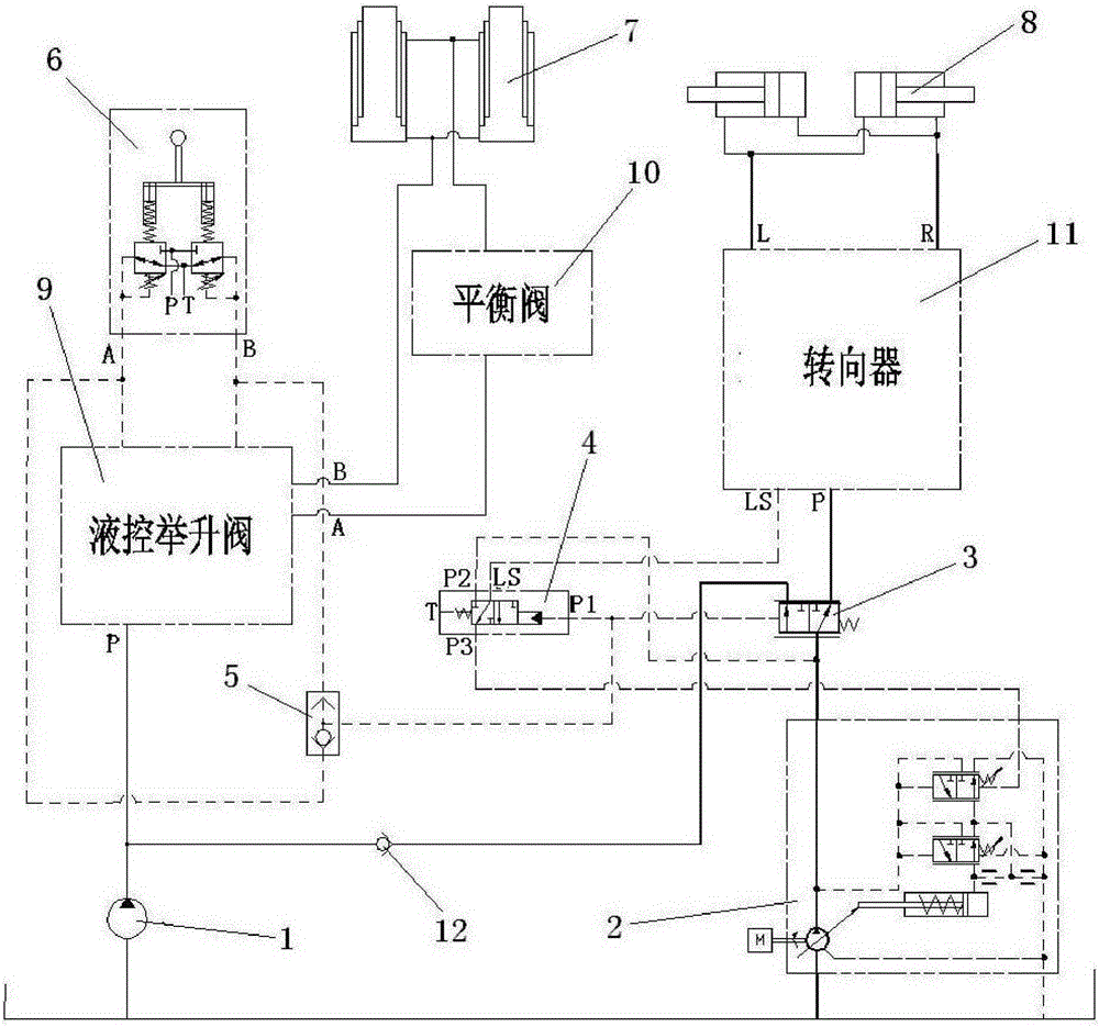
[0026] The specific implementation will be described below in conjunction with the accompanying drawings.

[0027] like image 3 As shown, in this embodiment, the fixed displacement hydraulic system of the mining dump truck includes a hydraulic lift system and a hydraulic steering system; wherein the hydraulic lift system includes a lift cylinder 7, a hydraulically controlled lift valve 9, a pilot valve 6, The balance valve 10, lift pump 1, and pump ports of lift pump 1 are connected to the P port of the hydraulic control lift valve, and the A and B ports of the pilot valve 6 are connected to the control oil port of the hydraulic control lift valve 9. Port A and port B of the lift valve 9 are connected to the lift cylinder 7, and the balance valve 10 is connected between the hydraulically controlled lift valve 9 and the lift cylinder 7, that is, connected to the small cavity oil port of the lift cylinder and the hydraulic control valve. Between the A ports of the lift valve; ...


PUM


Abstract

The invention relates to a fixed delivery and variable delivery hydraulic system of a mining dump truck. A hydraulic steering system in the fixed delivery and variable delivery hydraulic system of the mining dump truck comprises a steering oil cylinder, a load-sensitive variable pump, a steering gear, a signal control valve, a shuttle valve and a flow control valve, wherein the steering gear is connected with the steering oil cylinder. A control oil path of a pilot valve is simultaneously communicated with a signal port P1 of the signal control valve and a left end signal port of the flow control valve. A left position oil outlet of the flow control valve is in one-way communication with a port P of a hydraulic control lift valve through a check valve, a right position oil outlet of the flow control valve is connected with a port P of the steering gear, and an oil inlet of the flow control valve is connected with the pump opening of the load-sensitive variable pump. The pump opening of the load-sensitive variable pump is connected with a port P2 of the signal control valve, a port P3 of the signal control valve is connected with a valve LS in the load-sensitive variable pump, and a port LS of the signal control valve is connected with a port LS of the steering gear. The fixed delivery and variable delivery hydraulic system of the mining dump truck is stable in working and simple in structure, and reduces energy consumption.

Description

technical field [0001] The invention relates to a mine dump truck hydraulic system, in particular to a mine dump truck constant variable hydraulic system. Background technique [0002] Mining dump truck is a heavy-duty truck used to complete ore transportation tasks in open-pit mines. It is characterized by short transportation distances and strong carrying capacity. Excavation yards and unloading yards are widely used in metallurgy, non-ferrous metals, chemicals, coal and other earthwork transportation industries. Mining dump trucks are mainly composed of power system, transmission system, frame, cargo box, suspension system, steering system, hydraulic system, braking system, electrical system and covering parts. At present, the tonnage of mining dump trucks ranges from 20 tons Generally, the tonnage of mine trucks used in mines is in line with its output. For small mines with an annual output of one million tons, 25-50 tons of vehicles are used; for mines with an annual o...

Claims


Application Information

Patent Timeline
Patent Type & Authority Patents(China)
IPC IPC(8): B60P1/16B62D5/06
Inventor 杨胜清唐绪文王玉唐云娟
Owner GUANGXI LIUGONG MASCH CO LTD
Why Eureka
Try Eureka