
Band-type separating mechanism

A separation mechanism and band technology, applied in clutches, mechanical equipment, magnetic drive clutches, etc., can solve problems such as high noise, and achieve the effect of low noise and safe use

Inactive Publication Date: 2014-01-22
710TH RES INST OF CHINA SHIPBUILDING IND CORP
View PDF6 Cites 3 Cited by
  • Summary
  • Abstract
  • Description
  • Claims
  • Application Information

AI Technical Summary

Problems solved by technology

[0003] In order to overcome the above technical problems, the present invention provides a band-type separation mechanism, which can complete the separation of a large load with a small force, and overcomes the defect of large noise during separation

Method used


Image

  • Band-type separating mechanism
  • Band-type separating mechanism
  • Band-type separating mechanism

Examples


Embodiment Construction

[0024] The specific implementation of the present invention will be further described below in conjunction with the accompanying drawings and examples. The following examples are only used to illustrate the technical solutions of the present invention more clearly, but not to limit the protection scope of the present invention.

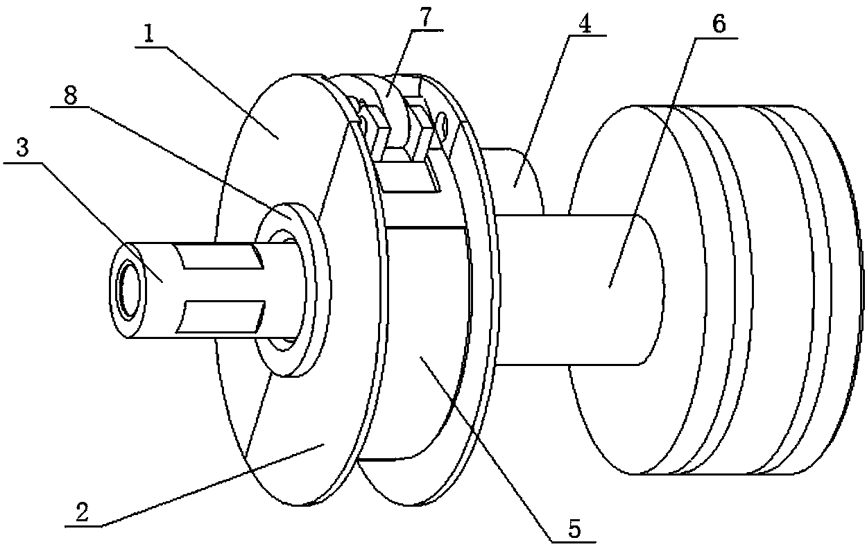
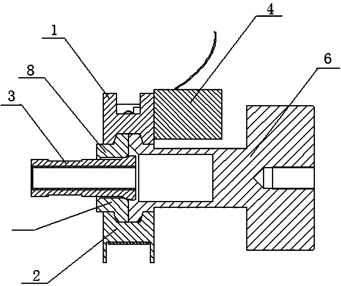
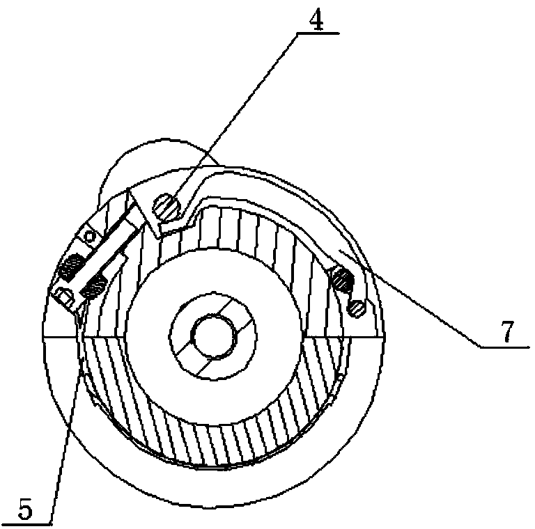
[0025] Such as Figure 1 to Figure 7 As shown, the technical solution for the specific implementation of the present invention is: a band-type separation mechanism, which is characterized in that it includes half a1, half b2, ball head rod 3, electromagnet 4, band group 5, and separation seat 6 , pressure rod 7 and adapter seat 8; its peripheral equipment is separating part 9 and to-be-separated part 10;

[0026] The half block a1 and the half block b2 are both semi-circular structures, and the half block a1 and the half block b2 are combined to form a circular ring structure. Trapezoidal grooves are formed, mounting grooves are formed on the outer p...


PUM

PropertyMeasurementUnit
Suctionaaaaaaaaaa
Journeyaaaaaaaaaa
Diameteraaaaaaaaaa

Abstract

The invention belongs to the technical field of separating devices, in particular to a band-type separating mechanism. The band-type separating mechanism comprises a half block a, a half block b, a bulb rod, an electromagnet, a band set, a separating base, a pressing rod and a turning-connection base. Periphery equipment comprises a separating piece and a piece to be separated. According to the band-type separating mechanism, force needed in load separating is decomposed step by step, and locking can be completed with little action force; when the band-type separating mechanism is used, by means of installation of a slope, the band set, the pressing rod and the like, separation load is decomposed step by step to be at a very small value, locking is completed through the electromagnet, separation can be finished as long as force needed by locking is overcome during separation, noise is low and use is safe during separation.

Description

technical field [0001] The invention belongs to the technical field of separation devices, and in particular relates to a band type separation mechanism. Background technique [0002] The traditional separation methods are mainly divided into two categories: mechanical actuator separation and pyrotechnic separation. When the workpiece with a small force is used to drive a large load to complete the separation requirements, most mechanical separation mechanisms cannot meet the use requirements; The main disadvantages of the separation mechanism are low safety and large separation noise during separation. Contents of the invention [0003] In order to overcome the above technical problems, the present invention provides a band-type separation mechanism, which can complete the separation of a large load with a small force, and overcomes the defect of high noise during separation. [0004] In order to achieve the above object, the technical solution of the present invention i...

Claims


Application Information

Patent Timeline
IPC IPC(8): F16D27/102
Inventor 吕维乐聂晓敏芦廷彬王伟
Owner 710TH RES INST OF CHINA SHIPBUILDING IND CORP
Learn More