Image forming apparatus

An image and exposure device technology, applied in the direction of electric recording process applying charge pattern, equipment for electric recording process applying charge pattern, electric recording technique, etc., can solve problems such as hindering loading and unloading

Active Publication Date: 2014-01-22
KYOCERA DOCUMENT SOLUTIONS INC
View PDF5 Cites 4 Cited by
  • Summary
  • Abstract
  • Description
  • Claims
  • Application Information

AI Technical Summary

Problems solved by technology

However, such a partition wall prevents the image forming unit from being attached to and detached from the main body of the image forming apparatus.

Method used


Image

  • Image forming apparatus
  • Image forming apparatus
  • Image forming apparatus

Examples


Embodiment Construction

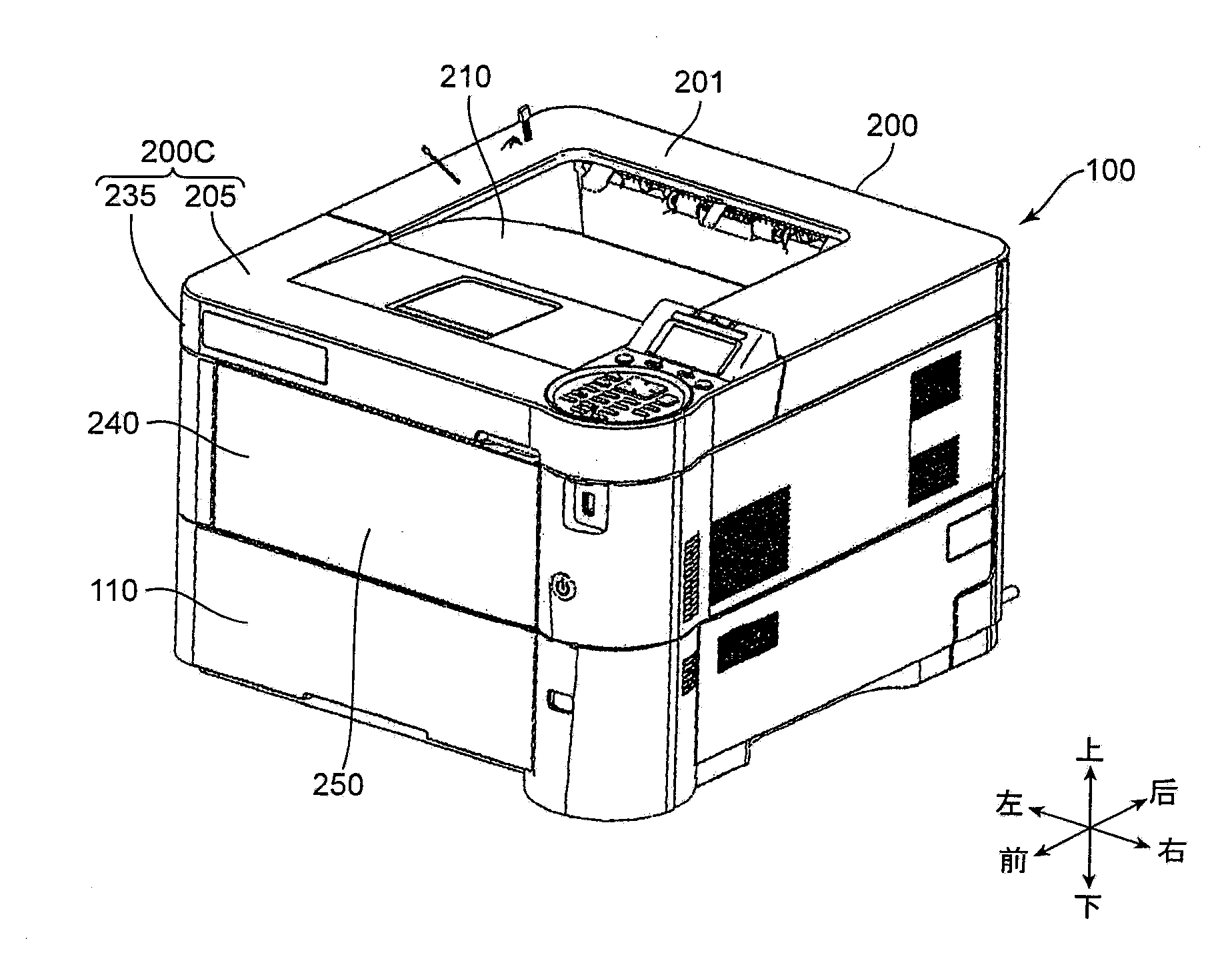
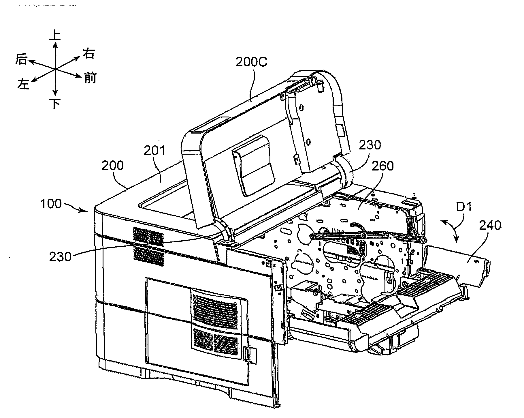
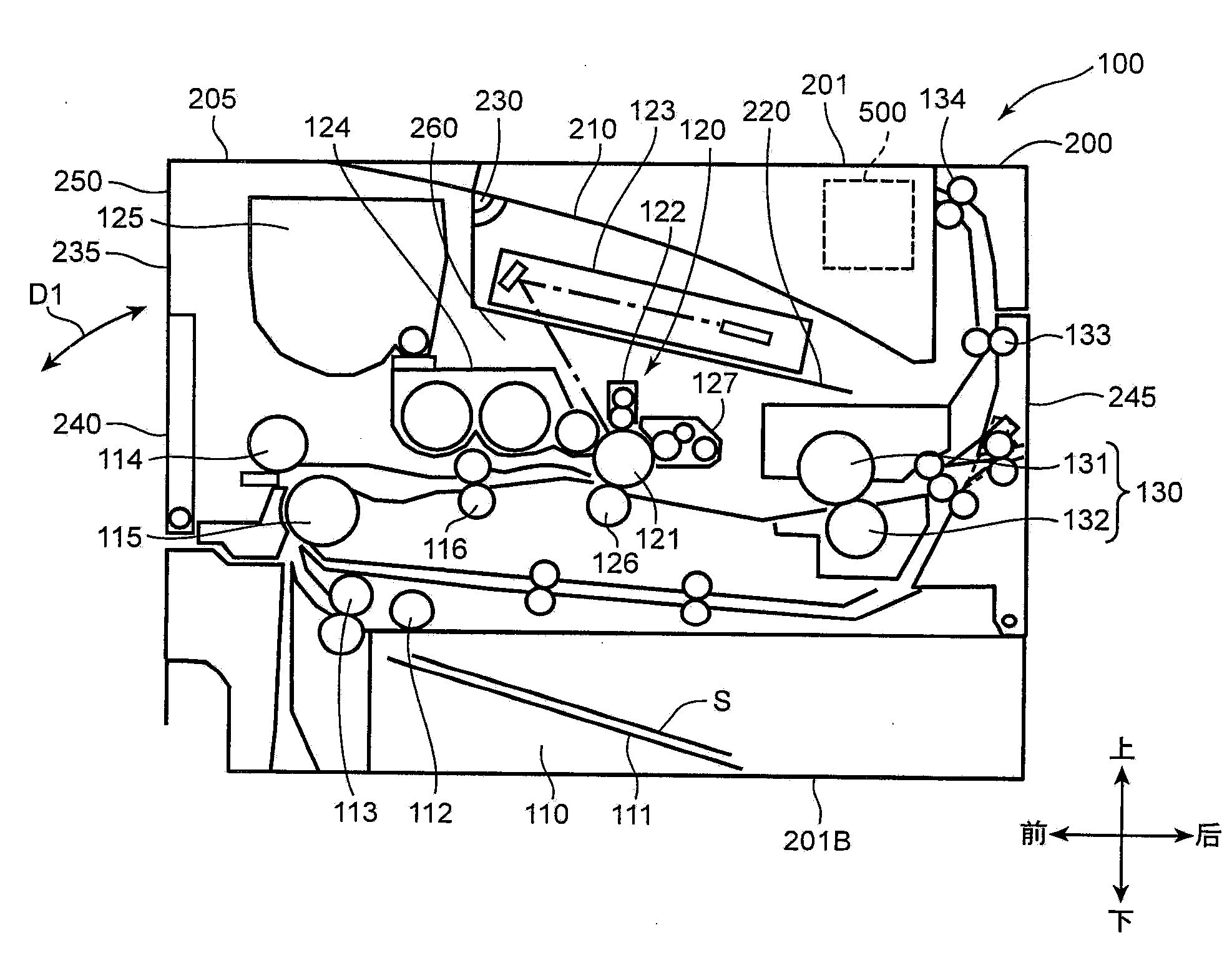
[0039] Hereinafter, an embodiment of the present invention will be described with reference to the drawings. figure 1 It is a perspective view of a printer 100 (image forming apparatus) according to an embodiment of the present invention. figure 2 It is a perspective view of the printer 100 in a state where an access cover 200C described later is opened upward and the manual feed tray 240 is opened downward. In addition, in figure 2 In , a state in which the cartridge 110 described later is drawn out is shown. in addition, image 3 is schematically shown figure 1 with figure 2 A cross-sectional view of the internal structure of the printer 100 is shown. Figure 1 to Figure 3 The illustrated printer 100 as an image forming device is a so-called monochrome printer, but in other embodiments, the image forming device may also be a color printer, a facsimile device, a digital multifunction Agents are like other devices formed on the sheet. In addition, terms indicating di...


PUM


Abstract

An image forming apparatus has a casing, an opening / closing cover, an exposure device, an image forming unit, an airflow generator, a cooling air path, and a partition member. The partition member is disposed between the exposure device and the image forming unit, and is configured to change a state thereof between a first state and a second state. The first state is such that the partition member constitutes part of the cooling air path when the opening / closing cover is in a closed state. The second state is such that the image forming unit is allowed to be dismounted from an inner space of the casing, while passing between the exposure device and the image forming unit when the opening / closing cover is in an opened state.

Description

technical field [0001] The present invention relates to an image forming apparatus that forms an image on a sheet, and more particularly, to an image forming apparatus that includes an exposure device that forms an electrostatic latent image on an image carrier. Background technique [0002] Conventionally, as an image forming apparatus for forming an image on a sheet, an apparatus including an exposure device and an image forming unit including a photosensitive drum and a developing device is known. An electrostatic latent image is formed on the photosensitive drum by an exposure device, and the electrostatic latent image is developed as a toner image by a developing device. [0003] The exposure unit has a laser diode and a dust-proof sealing glass inside its housing. Laser light emitted from the laser diode scans in the main scanning direction through a transparent sealing glass, and is guided to the drum surface of the photosensitive drum rotating in the sub scanning di...

Claims


Application Information

Patent Timeline
IPC IPC(8): G03G15/04G03G21/20G03G15/00
CPCG03G21/206G03G2221/1645
Inventor 浅川善行冨冈宏行
Owner KYOCERA DOCUMENT SOLUTIONS INC
Why Eureka
Try Eureka