Elevator

A technology of elevators and electric motors, which is applied in the direction of elevators, lifts, packaged items in buildings, etc.

Active Publication Date: 2010-11-17
MITSUBISHI ELECTRIC CORP +1
View PDF1 Cites 0 Cited by
  • Summary
  • Abstract
  • Description
  • Claims
  • Application Information

AI Technical Summary

Problems solved by technology

Therefore, in order to manufacture a variety of manual handles, it is quite costly, and it is also troublesome to select a manual handle suitable for the shaft diameter of each rotating shaft.

Method used


Image

  • Elevator
  • Elevator
  • Elevator

Examples


Embodiment approach 1

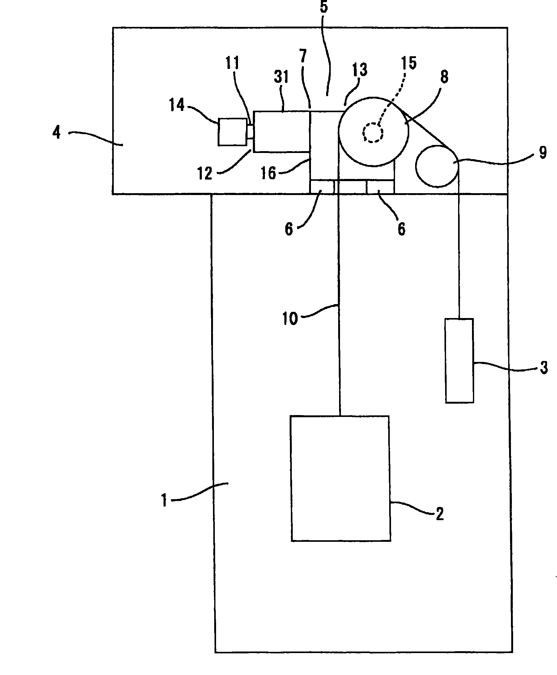
[0016] figure 1 It is a block diagram showing the elevator according to Embodiment 1 of the present invention. In the drawing, a car 2 and a counterweight 3 are provided in a hoistway 1 so that they can be raised and lowered. A machine room 4 is provided on the top of the hoistway 1 . In the machine room 4, a traction machine 5 is installed as a driving device. This traction machine 5 generates a driving force for raising and lowering the car 2 and the counterweight 3. The traction machine 5 is supported by a support member provided in the machine room 4. 6 on.

[0017] The hoisting machine 5 has a hoisting machine main body (drive device main body) 7 and a drive sheave 8 rotated by the hoisting machine main body 7 . In addition, a deflector sheave 9 arranged at a distance from the driving sheave 8 is provided in the machine room 4 .

[0018] A plurality of main ropes 10 are hung around the driving sheave 8 and the deflecting pulley 9 . The car 2 and the counterweight 3 ...

Embodiment approach 2

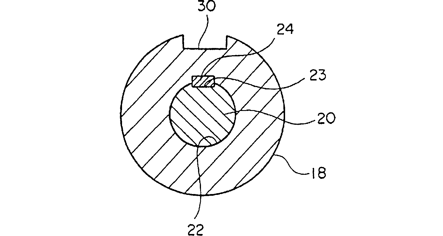
[0036] In the above example, one groove portion 30 is provided on the outer peripheral portion of the hub 18 as the anti-rotation portion, but a pair of groove portions arranged at symmetrical positions with respect to the axis of the motor shaft 11 may be provided as a pair of anti-rotation portions. on the outer periphery of the hub 18.

[0037] which is, Figure 4 It is a cross-sectional view of main parts showing a hoisting machine of an elevator according to Embodiment 2 of the present invention. also, Figure 4 is the same as in Embodiment 1 image 3 Corresponding sectional view. In the drawing, a pair of grooves (rotation stoppers) 41 arranged at symmetrical positions with respect to the axis of the motor shaft 11 are provided on the outer peripheral portion of the hub 18 . The cross-sectional shape of each groove part 41 is the same shape. Thus, the shape of the outer peripheral portion of the hub 18 is symmetrical with respect to the axis of the motor shaft 11 . ...


PUM


Abstract

A hoisting machine for an elevator includes a motor having a motor body and a rotary shaft rotatable with respect to the motor body and a boss, which is a handle fit / removal member and is fixed to the rotary shaft. Amanually operated handle for manually rotating the rotary shaft can be removably fitted on the boss. The boss is provided with a rotation prevention portion for preventing, when the manually operated handle is fixed to the boss, the manually operated handle from rotating with respect to the boss in a rotational direction of the rotary shaft.

Description

technical field [0001] The invention relates to an elevator for raising and lowering a car and a counterweight. Background technique [0002] In the conventional traction machine of an elevator, a manual handle is sometimes installed at the end of the rotating shaft of the motor, and the manual handle is used, for example, when the car stops between floors due to a power failure or malfunction. The handle used to move the car by manpower. An operator can move the car to the nearest floor by manually rotating the attached manual handle after attaching the manual handle to the rotation shaft of the motor (see Patent Document 1). [0003] Patent Document 1: Japanese Patent Laid-Open No. 2001-278560 [0004] However, in such a conventional traction machine, since the manual handle is directly attached to the rotating shaft, a plurality of traction machines having different shaft diameters with respect to the rotating shaft may require a plurality of different manual handles. ...

Claims


Application Information

Patent Timeline
Patent Type & Authority Patents(China)
IPC IPC(8): B66B11/04B65D85/10
CPCB65D5/606B66B11/0415B66B5/027B65D85/1045
Inventor 川上重信清水崇行斋藤俊一郎
Owner MITSUBISHI ELECTRIC CORP
Why Eureka
Try Eureka