

Novel umbrella-shaped antenna structure
An umbrella antenna, a new type of technology, applied in the direction of the radiating element structure, the combination of independent antenna units, etc., can solve the problems of passive use, the antenna has no beautifying effect, etc., and achieve good use effect.
Inactive Publication Date: 2014-01-22
纪宾
View PDF0 Cites 1 Cited by
- Summary
- Abstract
- Description
- Claims
- Application Information
AI Technical Summary
Problems solved by technology
[0002] So far, TV antennas have various shapes, most of which are composed of two retractable metal rods. Although the effect of TV antennas is acceptable, such antennas have no beautifying and decorative functions, so it is easy to cause passive use.
Method used
View moreImage
Smart ImageViewing Examples

Examples
Embodiment Construction
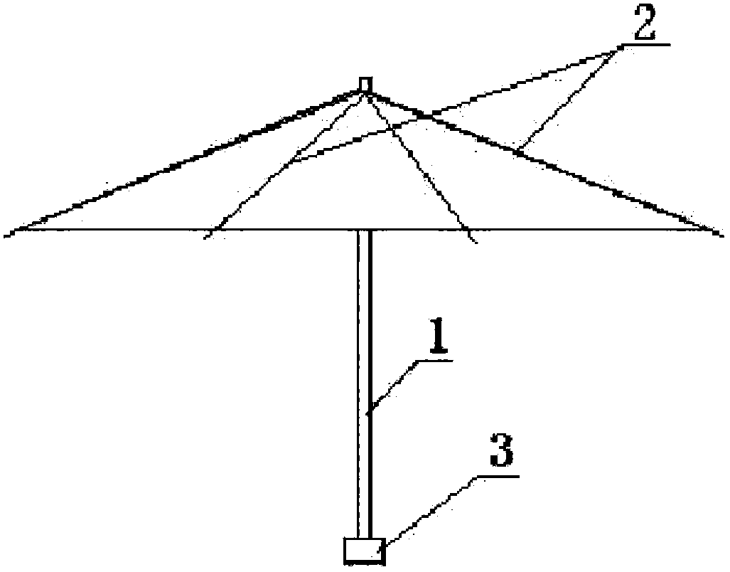
[0009] A new umbrella-shaped antenna structure, which is composed of: an umbrella-shaped antenna (1), an umbrella rib (2) and a signal amplifier (3); wherein, it sets the umbrella-shaped antenna (1) and the metal umbrella rib (2) separately It is a U-band or V-band vibrator of a TV antenna, and a signal amplifier (4) is arranged under the umbrella antenna (1).
Login to View More PUM
 Abstract
A novel umbrella-shaped antenna structure is disclosed. Umbrella ribs of an umbrella-shaped antenna are respectively set as U wave band or V wave band oscillators of a television antenna, a signal amplifier is arranged on the bottom end of the umbrella-shaped antenna, and thus the novel umbrella-shaped antenna structure can be obtained by connecting leading-out wires of the U wave band or V wave band oscillators on the umbrella-shaped antenna respectively to the signal amplifier and connecting an output end of the signal amplifier to a plug-in hole of the television antenna. The novel umbrella-shaped antenna structure has the advantages that the umbrella ribs of the umbrella-shaped antenna are respectively set as the U wave band or V wave band oscillators of the television antenna, the signal amplifier is arranged on the bottom end of the umbrella-shaped antenna, and the umbrella-shaped antenna structure can be used as a television antenna and has a beautification decoration effect of an umbrella shape, so that the usage effect is good.
Description
technical field [0001] The invention relates to an antenna structure, in particular to a novel umbrella-shaped antenna structure, which belongs to the technical field of television antennas. Background technique [0002] So far, TV antennas have various shapes, most of which are composed of two retractable metal rods. Although the effect of TV antennas is acceptable, such antennas have no beautifying and decorative functions, so it is easy to bring passive use. . Contents of the invention [0003] The purpose of the present invention is to provide a novel umbrella-shaped antenna structure, which can improve the existing problems of the current antenna, thereby bringing convenience in use. [0004] The technical solution adopted by the present invention to solve the technical problems is: a novel umbrella antenna structure, which is composed of an umbrella antenna, an umbrella rib and a signal amplifier; wherein, it sets the umbrella ribs of the umbrella antenna metal mate...
Claims
Login to View More Application Information
Patent Timeline
 IPC IPC(8): H01Q1/36H01Q21/30
Inventor纪宾
Owner纪宾