
Sub-conductive wire spacing bar

A technology of sub-conductor spacer bar and spacer bar, applied in the direction of maintaining the distance between parallel conductors, etc., can solve the problems of spacer bar breakage, easy to wear, low frame strength, etc., and achieve the effect of improving centripetal force, preventing mutual wear and improving strength.

Active Publication Date: 2014-01-22
STATE GRID CORP OF CHINA +2
View PDF4 Cites 1 Cited by
  • Summary
  • Abstract
  • Description
  • Claims
  • Application Information

AI Technical Summary

Problems solved by technology

[0002] The matching part between the frame of the sub-conductor spacer and the main body of the clamp for transmission lines is generally a circular structure. This kind of matching structure is prone to wear and tear on the matching part between the frame of the spacer and the main body of the clamp in the case of breeze vibration or strong wind, resulting in damage to the spacer or even Losing the protective function will affect the safety of the transmission line. In addition, the sub-conductor spacers used in the transmission line generally adopt a groove structure frame, which has low strength and is prone to wear and tear.

Method used


Image

  • Sub-conductive wire spacing bar
  • Sub-conductive wire spacing bar
  • Sub-conductive wire spacing bar

Examples


Embodiment Construction

[0009] The specific implementation manners of the present invention will be further described in detail below in conjunction with the accompanying drawings.

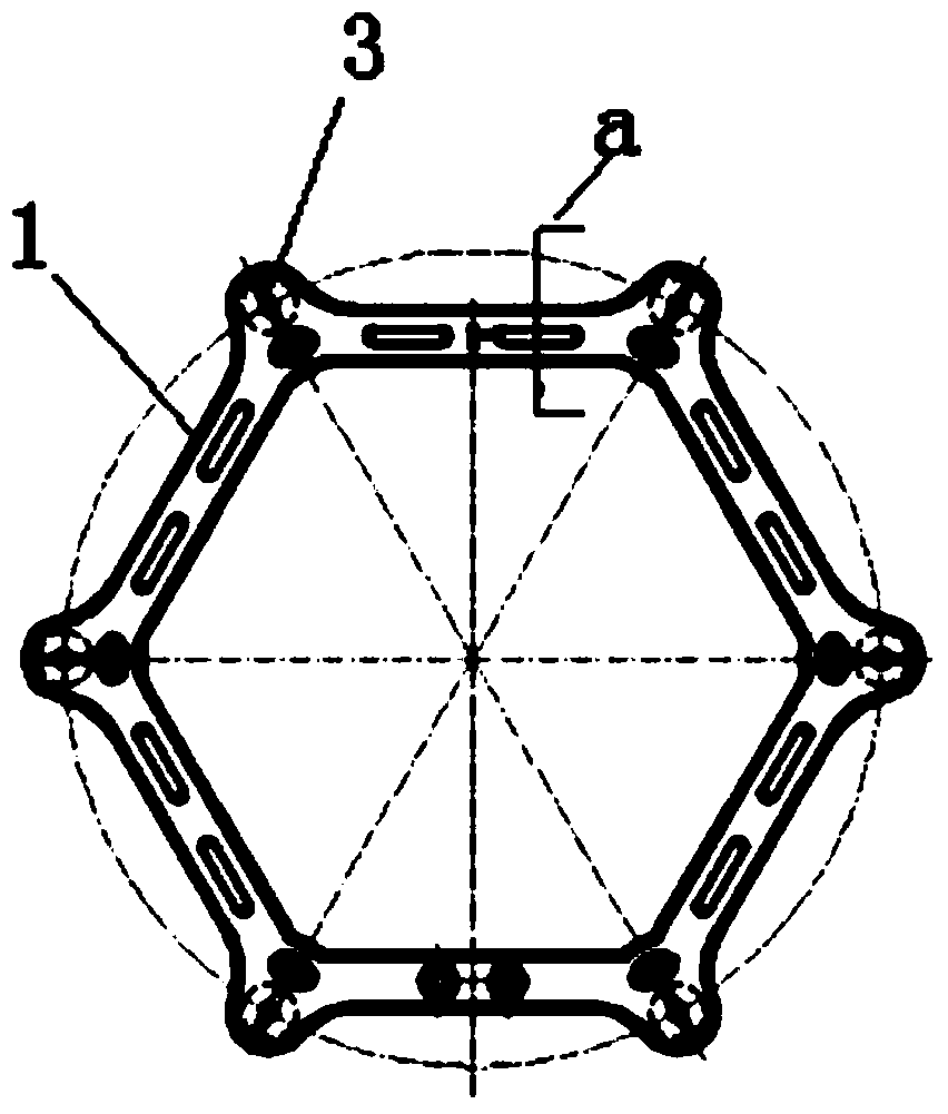
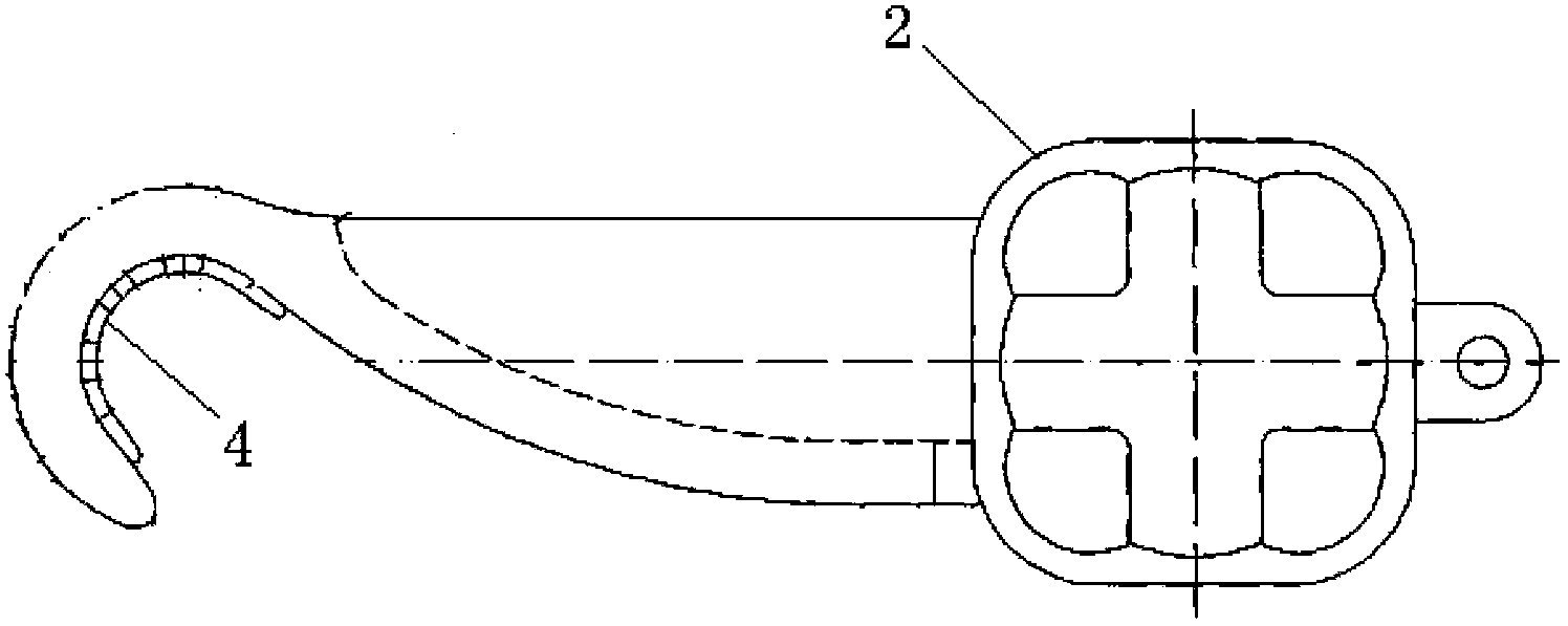
[0010] like figure 1 , figure 2 and image 3 In the shown embodiment, a seed wire spacer bar, the spacer bar includes a polygonal frame 1 and a clip body 2 connected to the frame 1, the head end of the clip body 2 is hook-shaped, and the hook The inner arc surface of the frame is provided with an elastic anti-skid protection pad 4, the cross-section of the frame 1 is I-shaped, the frame 1 and the clamp main body 2 are provided with through holes with different apertures, and the through holes with different apertures There is a tapered clamping part 3 connecting the frame 1 and the main body of the cable clamp 2 inside; a gap is formed between the frame 1 and the main body of the cable clamp 2 in the axial direction to avoid mutual wear of the two.

[0011] Another preferred embodiment of the present invention is tha...


PUM


Abstract

Provided is a sub-conductive wire spacing bar which comprises a polygon framework and a wire clamp body which is connected with the framework. The head end part of the wire clamp body presents to be a hooked shape. The internal arc surface of the hook is provided with an elastic anti-skid protective mat. The cross section of the framework presents to be H-shaped. The framework and the wire clamp body are provided with through holes with different hole diameters. The through holes with different hole diameters are internally provided with cone-shaped clamping pieces which are connected with the framework and the wire clamp body. A gap is arranged between axial directions of the framework and the wire clamp body of the spacing bar so that wearing caused by mutual friction between the framework and the wire clamp body is avoided.

Description

technical field [0001] The invention relates to a sub-wire spacer, in particular to a wear-resistant sub-wire spacer. Background technique [0002] The matching part between the sub-wire spacer frame and the main body of the clamp for transmission lines is generally a circular structure. This kind of matching structure is prone to wear and tear on the matching part between the spacer frame and the clamp body in the case of breeze vibration or strong wind, resulting in damage to the spacer or even Losing the protection function will affect the safety of the transmission line. In addition, the sub-conductor spacers used in the transmission line generally adopt a groove structure frame, which has low strength and is prone to wear and tear. Contents of the invention [0003] The object of the present invention is to provide a wear-resistant sub-wire spacer, which has high strength and is not prone to wear. [0004] The specific solution of the present invention is: a seed wir...

Claims


Application Information

Patent Timeline
Patent Type & Authority Applications(China)
IPC IPC(8): H02G7/12
Inventor 朱宽军牛海军司佳钧刘彬刘臻张军
Owner STATE GRID CORP OF CHINA
Learn More