Permanent magnet linear motor and permanent magnet array component thereof, as well as permanent magnet motor and component thereof

A permanent magnet linear motor and array component technology, applied in electric components, magnetic circuit static parts, magnetic circuit rotating parts and other directions, can solve problems such as limiting the output force of the motor, and achieve the effect of avoiding influence

Inactive Publication Date: 2014-01-22
肖俊东
View PDF10 Cites 10 Cited by
  • Summary
  • Abstract
  • Description
  • Claims
  • Application Information

AI Technical Summary

Problems solved by technology

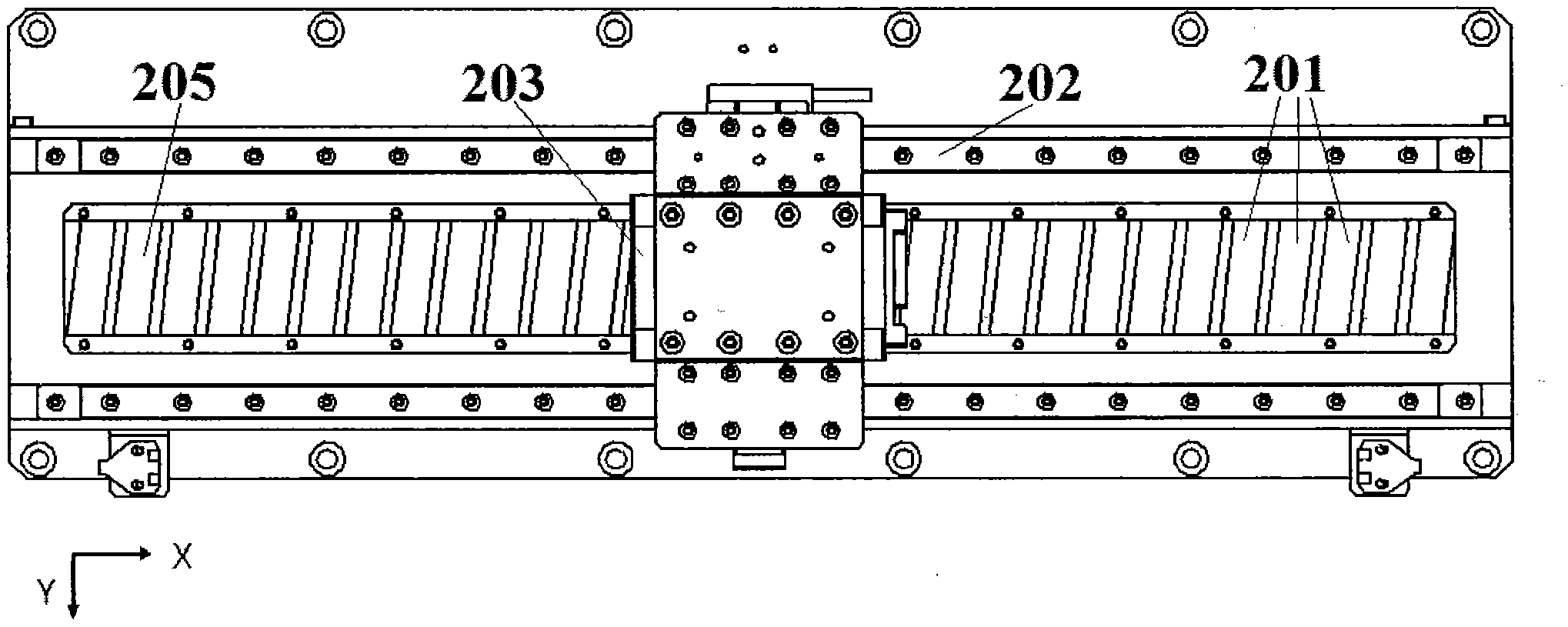
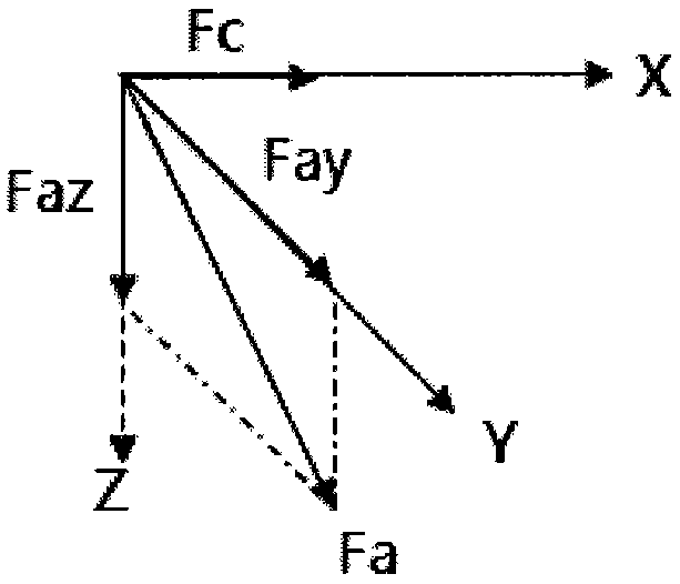
[0012] In order to facilitate manufacturing and reduce the oblique force, the length l of the permanent magnet 205 and the oblique angle θ (a larger oblique angle is beneficial to reducing the cogging force) cannot be selected too large, which limits the Increased motor output

Method used


Image

  • Permanent magnet linear motor and permanent magnet array component thereof, as well as permanent magnet motor and component thereof
  • Permanent magnet linear motor and permanent magnet array component thereof, as well as permanent magnet motor and component thereof
  • Permanent magnet linear motor and permanent magnet array component thereof, as well as permanent magnet motor and component thereof

Examples


Embodiment Construction

[0034] Embodiments of the present invention are described below with reference to the drawings.

[0035] One aspect of the present invention discloses a permanent magnet linear motor and a permanent magnet array assembly for the permanent magnet linear motor.

[0036] Figure 6 A schematic diagram of a permanent magnet linear motor according to the present invention is shown.

[0037] Such as Figure 6 As shown, a permanent magnet linear motor according to the present invention includes an armature winding (coil winding) 610 and a permanent magnet array assembly. The armature winding 610 and the permanent magnet array assembly are configured to be able to move relative to each other along a predetermined direction (also referred to as a "moving direction").

[0038] In the permanent magnet array assembly according to the present invention, the permanent magnet arrays 620, 625 are fixed on the mounting plate. In one embodiment, the length of the permanent magnet arrays 620,...


PUM


Abstract

The invention discloses a permanent magnet linear motor and a permanent magnet array component thereof, as well as a permanent magnet motor and a component thereof. The permanent magnet linear motor comprises an armature winding and the permanent magnet array component which are configured to move relatively in the preset direction. The permanent magnet array comprises two permanent magnet groups which are respectively configured on two sides of one straight line in the preset direction and symmetrical relative to the straight line; a plurality of permanent magnets in each permanent magnet group are arranged sequentially in the preset direction; the upper surface of each permanent magnet is far from a mounting plate; at least one part of the edge, adjacent to an adjacent permanent magnet in the same permanent magnet group, of the upper surface of each permanent magnet is neither parallel nor perpendicular to the preset direction. According to the invention, two groups of symmetrically and obliquely arranged permanent magnet arrays are used, so that obliquely arranged cogging force can be offset while the cogging force is reduced, and influence of the obliquely arranged cogging force on the precision and stability of motor operation is avoided.

Description

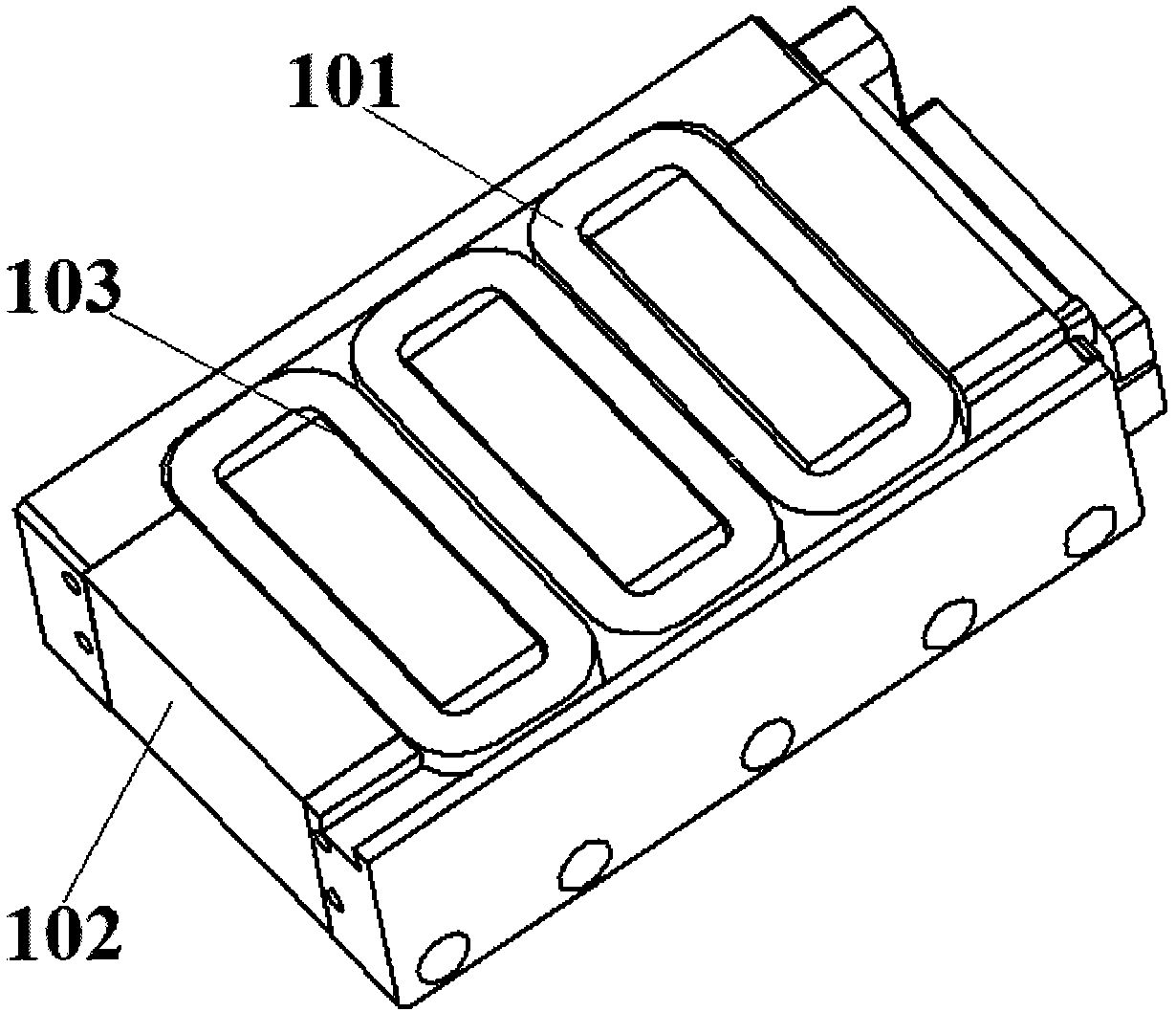
technical field [0001] The invention relates to a permanent magnet linear motor and its permanent magnet array assembly, a permanent magnet motor and its components. Background technique [0002] In order to improve the electromagnetic efficiency and the output force per unit volume of the motor in the design of the linear motor, an iron core structure is usually adopted. figure 1 The iron core structure of a conventional permanent magnet linear motor is shown, in which the motor coil 101 is embedded in the iron core 102 . [0003] In a linear motor having an iron core 102, the iron core 102 is generally provided with slots 103 for receiving the coil 101 therein. In this way, during the operation of the motor, the cogging force 103 on the iron core 102 will generate cogging force, which affects the accuracy and stability of the motor operation. [0004] In order to reduce the cogging force, oblique permanent magnets (such as magnets) are often used in the design of iron co...

Claims


Application Information

Patent Timeline
Patent Type & Authority Applications(China)
IPC IPC(8): H02K41/02H02K1/27H02K1/17
Inventor 肖俊东
Owner 肖俊东
Why Eureka
Try Eureka