Process and apparatus for cooling a digestion vessel of a calorimeter after use

A technology of decomposer and calorimeter, which is applied in the field of decomposer devices, can solve the problems of high cost and long time of the devices, and achieve the effects of avoiding cooling, economical distribution and uniform distribution

Active Publication Date: 2014-01-22
IKA WERKE
View PDF4 Cites 1 Cited by
  • Summary
  • Abstract
  • Description
  • Claims
  • Application Information

AI Technical Summary

Problems solved by technology

This cooling method and associated devices are expensive and take a long time to obtain sufficient cooling

Method used


Image

  • Process and apparatus for cooling a digestion vessel of a calorimeter after use
  • Process and apparatus for cooling a digestion vessel of a calorimeter after use
  • Process and apparatus for cooling a digestion vessel of a calorimeter after use

Examples


Embodiment Construction

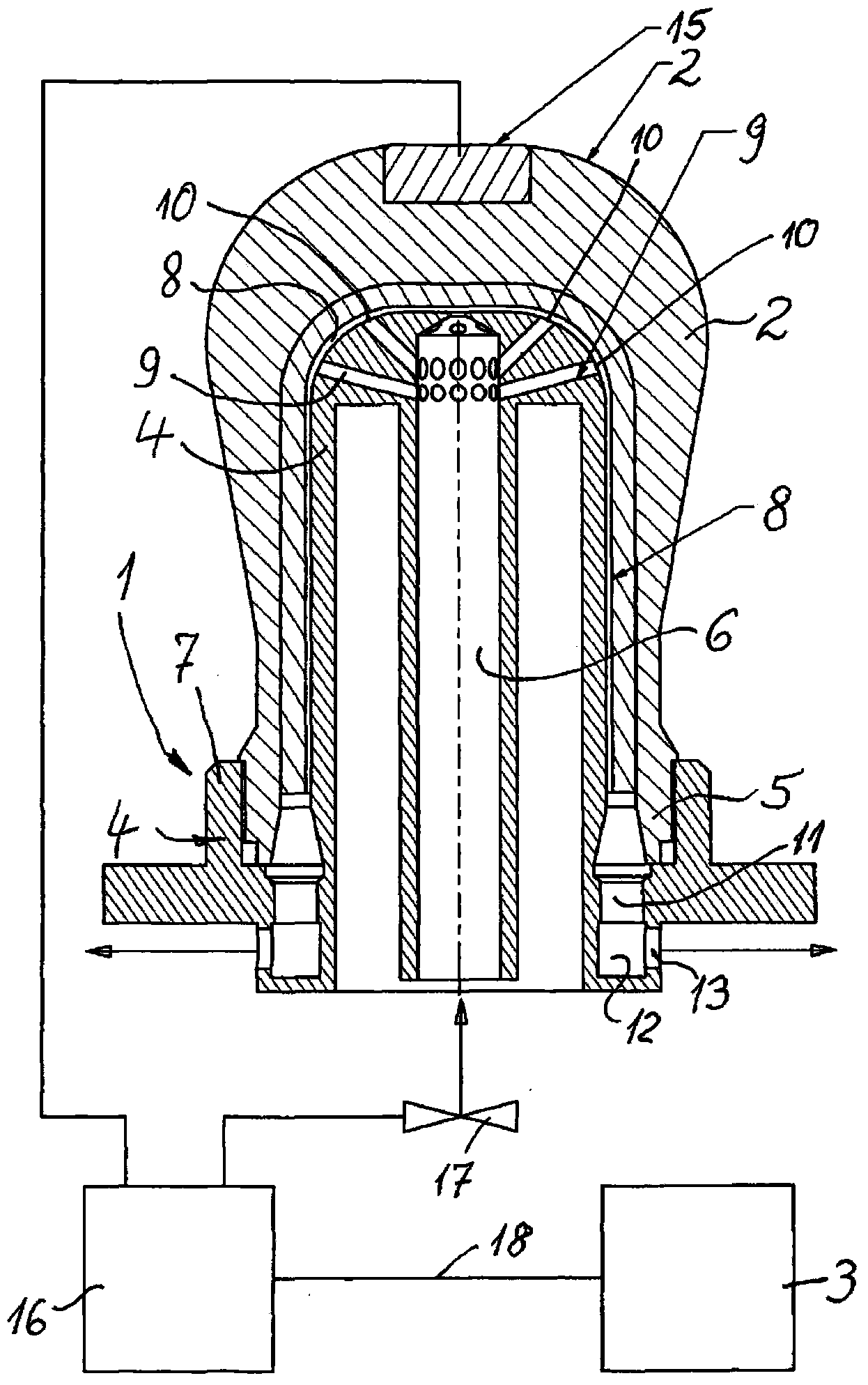
[0025] The device indicated as a whole by reference number 1 is used for cooling image 3 The decomposer 2 of the dry calorimeter 3 ( image 3 ). After use, such a decomposer 2 heats up considerably due to the combustion processes taking place therein, so it is particularly important that it can be returned to service as quickly as possible and that it can be recooled correspondingly quickly.

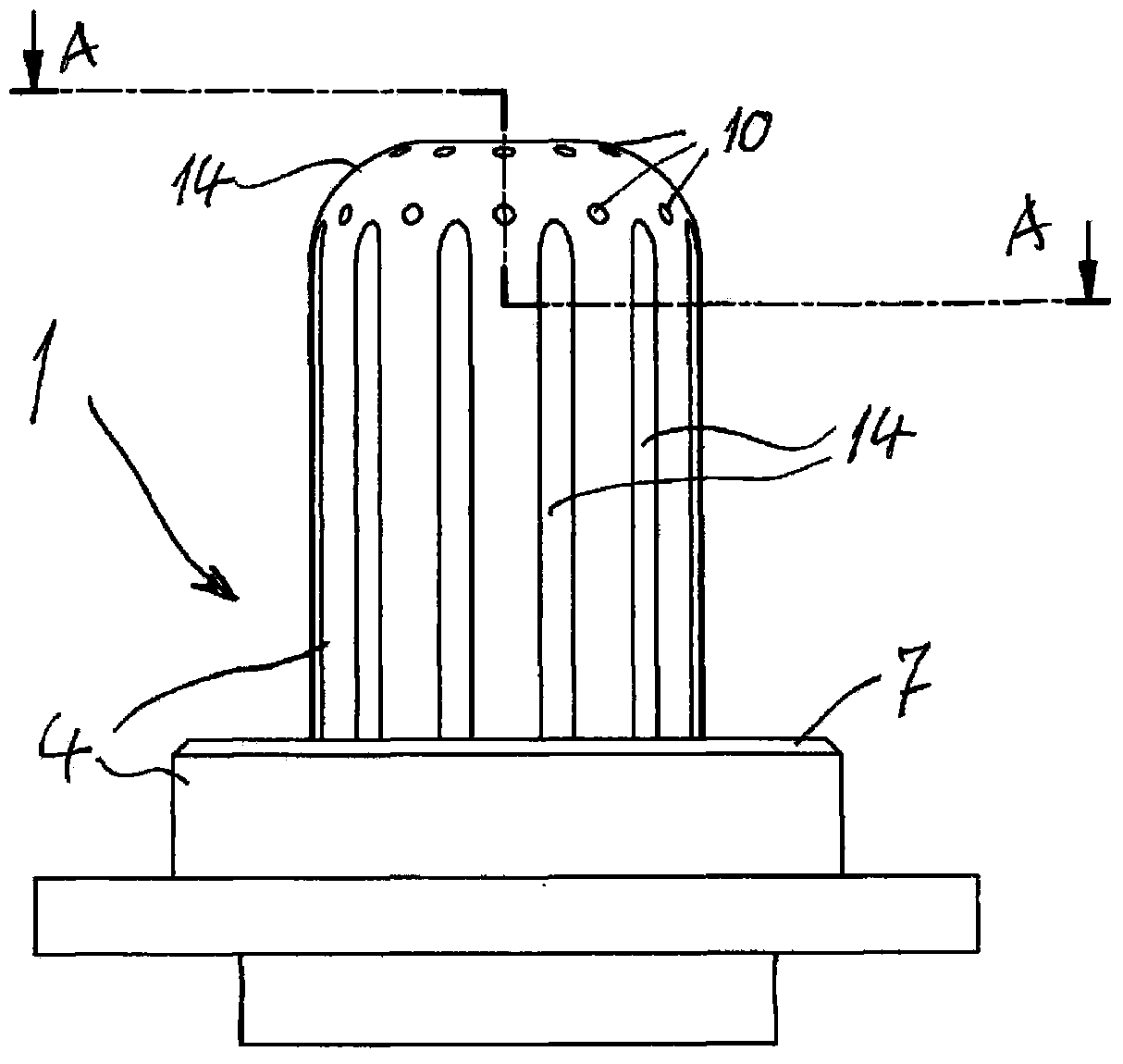
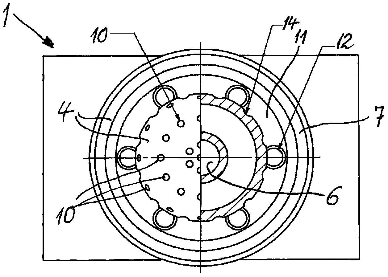
[0026] Device 1 also includes as figure 1 and figure 2 The bracket 4 shown, the bracket 4 is also defined as (in particular as image 3 The use position shown) accommodates the lower edge 5 of the resolver 2 or clamps the lower edge 5 of the resolver 2 during the cooling process.

[0027] Inside the bracket 4, people can image 3 Feed channels 6 for conveying coolant or cooling liquid, preferably water, are seen. This cooling liquid impinges on the upper surface of the support 4 and can thus wet the inner wall of the resolver 2 from the upper surface to cool it down.

[0028] re...


PUM


Abstract

To cool a digestion vessel (2) of a calorimeter (3) by means of a liquid coolant, a recess (4) over which the digestion vessel (2) is inverted during the cooling process and which has one or more ports (10) for a cooling liquid by means of which the inside of the digestion vessel (2) is wetted in such a way that the coolant runs down over part or the entire area of this inside of the digestion vessel (2) so as to remove the heat thereof is provided.

Description

technical field [0001] The invention relates to a method for cooling a decomposer of a dry calorimeter. After use, the decomposer is cooled to a certain temperature, thereby being applicable to subsequent use processes. [0002] The invention also relates to a device for cooling a decomposer of a dry calorimeter, after use, in particular with a coolant, for carrying out the aforementioned method. Background technique [0003] A dry combustion calorimeter with a decomposer is known from patent DE4314454C1. [0004] It is known to cool the decomposer after use with dry calorimeters, thereby making the decomposer more quickly available for the required reuse. Furthermore, it is known that the resolver is clamped between two clips surrounding the resolver, the inside of the clips being in thermal contact with the outside of the resolver and then cooling the inside. This cooling method and associated devices are expensive and require a long time to obtain sufficient cooling. ...

Claims


Application Information

Patent Timeline
Patent Type & Authority Applications(China)
IPC IPC(8): G01K17/00G01N25/48
CPCG01K17/00G01N25/20G01N25/4826F25D3/10F28C3/00
Inventor 休伯特·皮哈克
Owner IKA WERKE
Why Eureka
Try Eureka