Ejection cushion block structure of injection mould

An injection mold and ejection technology, which is applied in the field of ejector block structure, can solve the problems of unbalanced ejection of the mold, warping and deformation of the ejector plate, and inability to release the mold smoothly, and achieves a simple manufacturing process, stable and reliable work, and satisfactory Effects of structural and cosmetic requirements

Inactive Publication Date: 2014-01-29
江苏文光模具技术有限公司
View PDF4 Cites 1 Cited by
  • Summary
  • Abstract
  • Description
  • Claims
  • Application Information

AI Technical Summary

Problems solved by technology

For molds with a mold life of more than 100,000 molds, the ejector plate is repeatedly bumped by the ejection rod of the injection molding machine. The long-term impact force will eventually cause the ejector plate to warp and deform, resulting in unbalanced ejection of the mold and cracking of the plastic part. Injection defects such as inability to demould smoothly

Method used


Image

  • Ejection cushion block structure of injection mould
  • Ejection cushion block structure of injection mould

Examples


Embodiment Construction

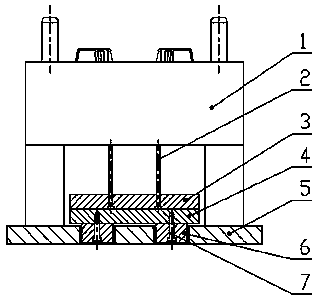
[0010] Depend on figure 1 It is known that an ejector block structure of an injection mold is composed of a movable template 1, an ejector pin 2, an ejector plate 3, an ejector plate 4, a foot doubler plate 5, an ejector block 6, and fixing screws 7. There is an thimble 2 under the moving template 1, and the thimble 2 is fixed on the thimble plate 3, and the thimble panel 4 is fixed on the mold foot doubler 5, and the feature is that the mold foot doubler 5 is also provided with an ejection pad 6 , The ejector block 6 and the thimble panel 4 are connected by screws 7 . The diameter and height of the ejection pad 6 and the thimble panel 4 are consistent, which facilitates the replacement of the ejection pad 6 .

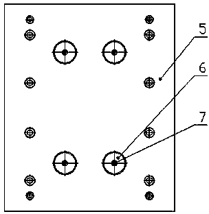
[0011] Depend on figure 2 It is known that it is a top view of the mold foot compound board. The mold foot doubler plate 5 is provided with four through holes for installing ejection pads 6 , and the mold foot doubler plate 5 ejects the pads 6 and is fixed with fix...


PUM


Abstract

The invention provides an ejection cushion block structure of an injection mould. The ejection cushion block structure is composed of a movable template (1), a thimble (2), a thimble plate (3), a thimble panel (4), a mould foot compound plate (5), an ejection cushion block (6) and a fixed screw (7), wherein the thimble (2) is arranged below the movable template (1); the thimble (2) is fixed on the thimble plate (3); the mould foot compound plate (5) is fixedly provided with the thimble panel (4). The ejection cushion block structure is characterized in that the mould foot compound plate (5) is further provided with the ejection cushion block (6); the ejection cushion block (6) and the thimble panel (4) are connected by the screw (7). According to the ejection cushion block structure of the injection mould, the ejection cushion block is mounted on an ejection position of the thimble panel; in an injection molding process, an ejection stick of an injection molding machine is not directly acted on the thimble panel but collides with the ejection cushion block so that the ejection cushion block can be replaced conveniently at the later period, and the balance and the smooth ejection of a molded part at a de-molding phase can be realized. The ejection cushion block structure of the mould is simple and feasible, is stable and reliable to work, is simple in production process and is low in cost.

Description

technical field [0001] The invention relates to an injection mold, in particular to an ejection pad structure in a demoulding mechanism of the injection mold. Background technique [0002] Injection molding is now the main method of forming thermoplastics, so it has a wide range of applications. Injection molding is to put plastic raw materials into the barrel, heat and melt it to make it a high-viscosity melt, use a plunger or screw as a pressure tool, and inject the melt into the cavity of the mold through the nozzle at a higher pressure , after cooling and solidification stages, and then come out of the mold to become a plastic product. [0003] After the plastic part is solidified in the cavity, it must be taken out of the cavity mechanically, and this action must be completed by the demoulding mechanism. Unreasonable demoulding mechanism has a great impact on the quality of plastic parts, and the geometry of plastic parts is also ever-changing, so the most effective a...

Claims


Application Information

Patent Timeline
Patent Type & Authority Applications(China)
IPC IPC(8): B29C45/40B29C45/26
CPCB29C45/4005
Inventor 邬新桥卢建生陈栗刘伟汪双龙宋栗栗戎煜张静周樱
Owner 江苏文光模具技术有限公司
Why Eureka
Try Eureka