Conveying chain

A technology of conveying chain and chain plate, applied in the field of conveying chain, can solve the problems of affecting the life of conveying chain, unfavorable cost saving, easy aging of pins, etc., and achieve the effect of improving efficiency, prolonging service life and saving cost.

Inactive Publication Date: 2014-01-29
CHANGZHOU DONGWU CHAIN TRANSMISSION MFGCO
View PDF0 Cites 2 Cited by
  • Summary
  • Abstract
  • Description
  • Claims
  • Application Information

AI Technical Summary

Problems solved by technology

[0002] The chain plates of the traditional conveyor chain are connected by pins. When the pins are under pressure, they collide with the pin holes and squeeze without any buffer, which makes the pins easy to age and affects the life of the conveyor chain, which is not conducive to saving costs.

Method used


Image

  • Conveying chain

Examples


Embodiment Construction

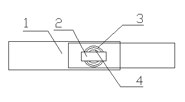
[0011] Such as figure 1 It is a structural schematic diagram of the present invention, a conveyor chain, including a chain plate 1, a pin shaft 2 and a pin hole 3, the chain plate 1 is provided with a pin hole 3, the pin shaft 2 passes through the pin hole 3 and is positioned and connected with the chain plate 1, and the pin A protective layer 4 is provided on the edge of the inner hole of the hole 3, and the protective layer 4 is an annular elastic rubber layer, and the protective layer 4 is completely attached to the inner edge of the pin hole 3.

[0012] A layer of rubber protective layer 4 with cushioning function is built into the edge of the pin hole 3, and then the pin shaft 2 is inserted therein. When the pin shaft 2 is subjected to external pressure and the pin hole 3 is squeezed each other, the protective layer 4 can absorb a large amount of Partial pressure prevents the pin shaft 2 from being deformed and aged. The use of the conveyor chain can reduce the external p...


PUM


Abstract

The invention relates to a transport mechanism, in particular to a conveying chain. The conveying chain comprises a chain board, a hinge pin and a pin hole, wherein the pin hole is formed in the chain board, and the hinge pin penetrates through the pin hole and is connected with the chain board in a positioned mode; a protecting layer is arranged at the inner edge of the pin hole, wherein the protecting layer is an annular elastic rubber layer, and the protecting layer is completely attached to the inner edge of the pin hole. By means of the conveying chain, external pressure borne by the hinge pin can be reduced, the service life of the conveying chain is prolonged, cost is reduced, and effects are improved.

Description

technical field [0001] The invention relates to a transmission mechanism, in particular to a conveyor chain. Background technique [0002] The chain plates of the traditional conveyor chain are connected by pins. When the pins are under pressure, they collide with the pin holes and squeeze without any buffer. As a result, the pins are easy to age and affect the life of the conveyor chain, which is not conducive to saving costs. Contents of the invention [0003] In order to overcome the shortcoming that the pin shaft of the existing conveyor chain is easy to age, the invention provides a conveyor chain. [0004] The technical scheme adopted by the present invention to solve the technical problem is: a conveyor chain, including a chain plate, a pin shaft and a pin hole, the chain plate is provided with a pin hole, the pin shaft passes through the pin hole and is positioned and connected with the chain plate, A protective layer is provided on the edge of the hole. [0005]...

Claims


Application Information

Patent Timeline
Patent Type & Authority Applications(China)
IPC IPC(8): B65G17/38
Inventor 吴国平
Owner CHANGZHOU DONGWU CHAIN TRANSMISSION MFGCO
Why Eureka
Try Eureka