Thrombectomy equipment

A technology of equipment and bracket structure, applied in the field of thrombectomy equipment, can solve problems such as detrimental equipment efficiency and little success, and achieve the effect of improving shearing effect

Active Publication Date: 2017-11-24
PHENOX
View PDF3 Cites 0 Cited by
  • Summary
  • Abstract
  • Description
  • Claims
  • Application Information

AI Technical Summary

Problems solved by technology

[0006] A drawback of these thrombolytic therapies is that they are rarely successful after the relevant time frame requirements have expired
Specifically, the method of attachment to the guidewire via a tapered structure (teardrop shape) causes the proximal region of the structure to become thinner or elongated under tension, which compromises the efficiency of the device

Method used


Image

  • Thrombectomy equipment
  • Thrombectomy equipment
  • Thrombectomy equipment

Examples


Embodiment Construction

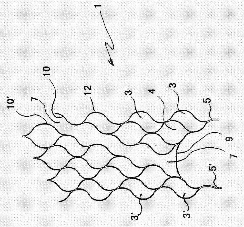
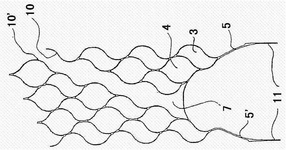
[0041] figure 1 and 3 Two variants of the inventive cylindrical stent structure 1 are shown, wherein individual meshes 3 and 4 and connectors 5 and 5' are shown. Mesh 3 and 4 are different shapes, mesh type (3) has a wavy form and mesh type (4) is more rounded in form and has two points. These two interacting mesh types / shapes provide stability and flexibility to the overall device structure.

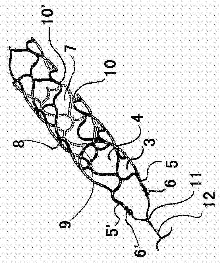
[0042] exist figure 1 and 3 In plan view in , slots or tubes 7 extend through the stent structure, said slots being spanned by retaining clips 9 at the proximal end of the structure. The groove 7 is bounded by the edges 10 and 10' of the mesh structure. The slots 7 will not be parallel to the longitudinal axis of the structure, but will be oriented obliquely to it, so that in a spatial view the slots run in a helical configuration along the generating surface of the device (cf. figure 2 / 4).

[0043] figure 1 and 3 A plan view of the cut-away stent structure 1 is shown; t...


PUM


Abstract

The invention relates to a thrombectomy device having a substantially cylindrical stent structure (1) comprising a plurality of meshes (3, 4) and two connectors (5, 5'), the connectors (5 , 5') arranged at different meshes (3) on the proximal end of the stent structure (1), the device also has a guide wire (2) equipped with a coupling element (11), a connector (5, 5') Attached to the coupling element (11), the device also has a groove (7) extending in a helical or coiled manner on the generated surface (8) of the stent structure (1), the device also has a transverse Fixing clip (9) spanning slot (7).

Description

technical field [0001] The present invention relates to a thrombectomy device having a substantially cylindrical stent structure comprising a plurality of meshes and two connectors arranged at different meshes at the proximal end of the stent structure, the thrombectomy device also comprising a coupling The guidewire of the coupling element to which the connector is attached. In particular, thrombectomy devices are used to remove clots / thrombus in a patient in a gentle and reliable manner that occur in brain regions that are commonly encountered during stroke-like. [0002] Thromboembolic diseases such as myocardial infarction, pulmonary embolism, peripheral thrombosis, organ embolism, etc. are usually caused by thromboembolism (hereinafter simply referred to as clot or thrombus), that is, viscoelasticity including platelets, fibrinogen, coagulation factors, etc. A blood clot, which forms in a blood vessel, completely or partially blocks the blood vessel. Blockage of an orga...

Claims


Application Information

Patent Timeline
Patent Type & Authority Patents(China)
IPC IPC(8): A61B17/221A61F2/91
CPCA61B17/221A61B2017/00867A61B2017/22038A61B2017/2215A61F2/91A61F2002/9505A61F2002/9528A61F2002/9534A61F2230/0019A61F2230/0026A61F2/90
Inventor H·蒙斯塔特R·汉内斯J·阿斯车菲德
Owner PHENOX
Why Eureka
Try Eureka