Feeding device of drilling equipment of lamp

A technology for punching equipment and feeding devices, which is applied in the direction of feeding devices, positioning devices, storage devices, etc., can solve problems such as low efficiency, insufficient punching accuracy, large errors, etc., and achieve improved quality, better automatic feeding, and improved The effect of efficiency and precision

Inactive Publication Date: 2014-02-05
德清县翔鹰金属制品有限公司
View PDF15 Cites 2 Cited by
  • Summary
  • Abstract
  • Description
  • Claims
  • Application Information

AI Technical Summary

Problems solved by technology

This kind of punching step has the following defects: one is that the manual operation is used to punch holes, and the efficiency is very low; the other is that the manual operation is not accurate enough to punch holes, and large errors wi

Method used


Image

  • Feeding device of drilling equipment of lamp

Examples


Embodiment Construction

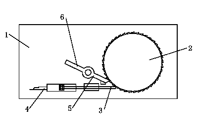
[0010] Combine below figure 1 Specific description embodiment:

[0011] A feeding device for lamp punching equipment, characterized in that the feeding device for lamp punching equipment includes a frame 1, and a toothed plate 2 is movable on the frame 1, and the toothed plate 2 The side is provided with a rack, and the frame 1 is provided with a push rod 3, one end of the push rod 3 is connected with a linkage rod 4, and the other end of the push rod 3 is connected to the linkage rod 4. Under the action, the toothed disc 2 can be driven to rotate, and the frame 1 is hingedly provided with an anti-rotation rod 5, and one end of the anti-rotation rod 5 is engaged with the rack.

[0012] Preferably, the other end of the anti-rotation rod 5 is connected with a wrench 6, and the wrench 6 can separate the anti-rotation rod 5 from the rack.

[0013] In the feeding device of the lamp punching equipment provided by the present invention, when in use, the lamp parts are placed on the...


PUM


Abstract

The invention belongs to the technical field of lamp tools, and particularly relates to a feeding device of drilling equipment of a lamp. The invention discloses the feeding device of the drilling equipment of the lamp. The feeding device of the drilling equipment of the lamp is characterized by comprising a frame, wherein a fluted disc is movably arranged on the frame, a rack is arranged at the side of the fluted disc, a push rod is arranged on the frame, one end of the push rod is connected with a connecting rod, the other end of the push rod can push the fluted disc to rotate under the action of the connecting rod, the frame is hinged to a rotation stopping rod, and one end of the rotation stopping rod is clamped with the rack. According to the feeding device, automatic feeding is well realized for punching the lamp, the efficiency and the precision of punching are improved, and the quality of products is improved.

Description

technical field [0001] The invention belongs to the technical field of lamps and appliances, and in particular relates to a feeding device for lamp punching equipment. Background technique [0002] During the manufacturing process of the lamp, holes are punched for its parts. The traditional method of punching holes in the lamps is to manually place the parts under the punching machine, and then step on the switch of the punching machine to make the punching machine press down, and then carry out the punching of the lamp parts. Punch. After punching a hole, then move the lamp parts, carry out the second punching step, and punch holes in sequence. There are following defects in this type of punching step: one is that manual operation is used for punching, which is very inefficient; At present, some factories have certain automatic punching equipment, but this kind of equipment has defects in the feeding of lamp parts, which leads to the accuracy and continuity of punching,...

Claims


Application Information

Patent Timeline
IPC IPC(8): B21D43/14B26D7/06
Inventor 沈昌荣
Owner 德清县翔鹰金属制品有限公司
Why Eureka
Try Eureka