
Disc Shearing Device and Its Composite Bushing

A technology of disc shears and bushings, which is applied to shearing devices, knives for shearing devices, metal processing equipment, etc., and can solve the problem of strip steel shearing and bending deformation, elastic deformation of shear blades and fixed sleeves and other problems, to achieve stable performance, high reliability, and reduce the effect of printing

Active Publication Date: 2016-08-17
LAIWU STEEL YINSHAN SECTION CO LTD
View PDF5 Cites 0 Cited by
  • Summary
  • Abstract
  • Description
  • Claims
  • Application Information

AI Technical Summary

Problems solved by technology

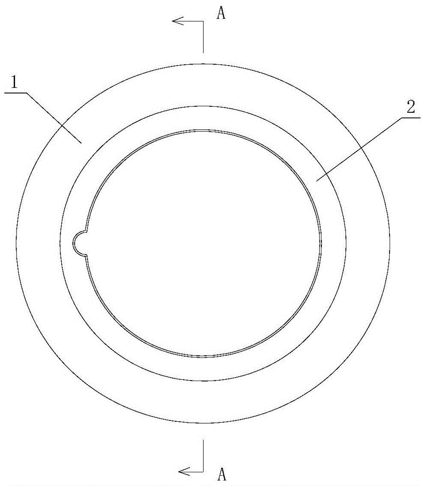
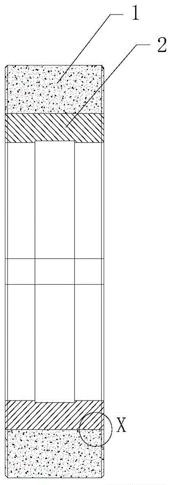
[0005] The purpose of the present invention is to provide a disc shearing device and its composite bushing, so as to solve the problem in the prior art that the strip steel may be bent and deformed during shearing due to the inconsistent elastic deformation of the shearing blade and the fixed sleeve

Method used


Image

  • Disc Shearing Device and Its Composite Bushing
  • Disc Shearing Device and Its Composite Bushing
  • Disc Shearing Device and Its Composite Bushing

Examples


Embodiment Construction

[0017] The present invention will be described in further detail below in conjunction with the accompanying drawings and specific embodiments.

[0018] The working speed of the trimming disc shears for cold-rolled annealed strip steel is 260-300m / min. When using the disc shearing device to cut, the trimming action is mainly completed by the simultaneous rotation of the upper and lower shear blades. When the steel strip is straight and stable, the upper and lower fixing sleeves are used to clamp the steel strip. Therefore, as well-known, in the disc shearing device, mainly comprise upper cutting edge, lower cutting edge, upper knife shaft, lower knife shaft, the upper fixing sleeve that provides the usefulness of positioning for upper cutting edge and provide for lower cutting edge. The lower fixed sleeve used for positioning, the upper cutting blade and the upper fixed sleeve are fixed on the upper knife shaft, and the lower shear blade and the lower fixed sleeve are fixed on ...


PUM


Abstract

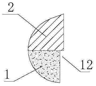
The present invention provides a disc shear device and a composite bushing thereof. The disc shear composite bush includes: a hard bush, which is in a ring structure, and is used to be fixedly sleeved on the knife shaft of the disc shears; The soft bushing is fixedly sleeved on the outside of the hard bushing, and is used to make the combined elastic deformation of the hard bushing and the soft bushing equal to that of the disc when the disc shears the strip steel. Elastic deformation of the shear blade. The invention has the characteristics of stable performance and high reliability, and has positive significance for reducing disc shear marks and improving the surface quality of strip steel.

Description

technical field [0001] The invention belongs to the technical field of steel rolling and finishing equipment, and in particular relates to a disc shearing device and a composite bushing for finishing cold-rolled strip steel. Background technique [0002] At present, the disc shearing device of the cold-rolled strip steel finishing system mainly includes an upper shear blade, an upper shear blade fixed sleeve, a lower shear blade, a lower shear blade fixed sleeve, and a hydraulic nut locker. Wherein, the main function of the lower shear blade fixed sleeve and the upper shear blade fixed sleeve is the positioning during the working process of the disc shears. During the strip shearing process, the disc shear blade will undergo elastic deformation due to the shear force, and the strip steel will also bend due to the shear force in the edge area of ​​the shear blade. It mainly plays a supporting role in the bending area of ​​the strip steel to decompose the force on the edge ar...

Claims


Application Information

Patent Timeline
Patent Type & Authority Patents(China)
IPC IPC(8): B23D35/00
Inventor 康华伟尹翠兰王春刚韩光燕栾贻忠吴庚亮张晓东
Owner LAIWU STEEL YINSHAN SECTION CO LTD
Learn More