Mechanical brake actuator

Active Publication Date: 2009-11-26
AH BRAKE CO LTD
View PDF5 Cites 0 Cited by
  • Summary
  • Abstract
  • Description
  • Claims
  • Application Information

AI Technical Summary

Benefits of technology

[0010]In order to attain the above objects, a mechanical brake actuator related to the invention is characterized to comprise a strut that has two facing plates with a strut-bridge connecting therebetween and that engages with first brake shoe, a brake lever that engages with second brake shoe, in which the brake lever is retained in a space between the facing plates of the strut and is pivotally supported in the strut at a proximal end thereof, and the brake lever and the strut relatively rotate to spread apart from each other while pulling a brake cable connected to a free end of the

Problems solved by technology

(1) An independent clip is more complex in assembly and leaves a possibility of losing the clip and/or to neglect the clip assembling.
(2) If the clip is assembled on the strut, a rotational axis needs to be on both outer surfaces of the strut, which increases the manufacturing cost.
(3) Because of providing the convex and the rotational axis on the strut, high accuracy in the formation of the projection and the rotational axis (i.e., coaxially) is necessary, which requires higher manufacturing accuracy.
(4) At least, the clip plate thickness becomes easily interfering with nearby parts such as a shoe return spring adjacent to the strut.
Therefore, operability as attaching the clip to the strut is jeopard

Method used


Image

  • Mechanical brake actuator
  • Mechanical brake actuator
  • Mechanical brake actuator

Examples


embodiment 1

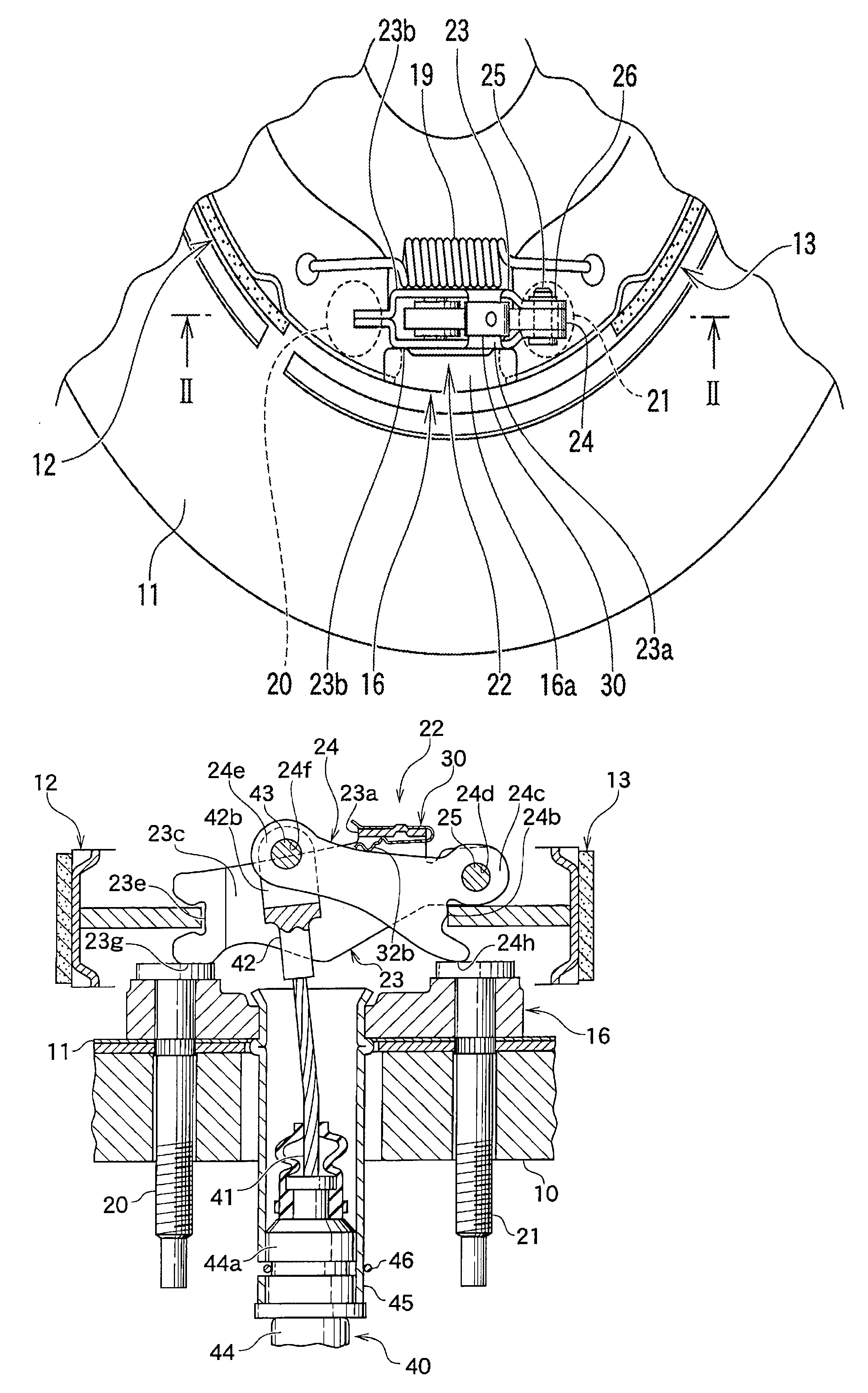
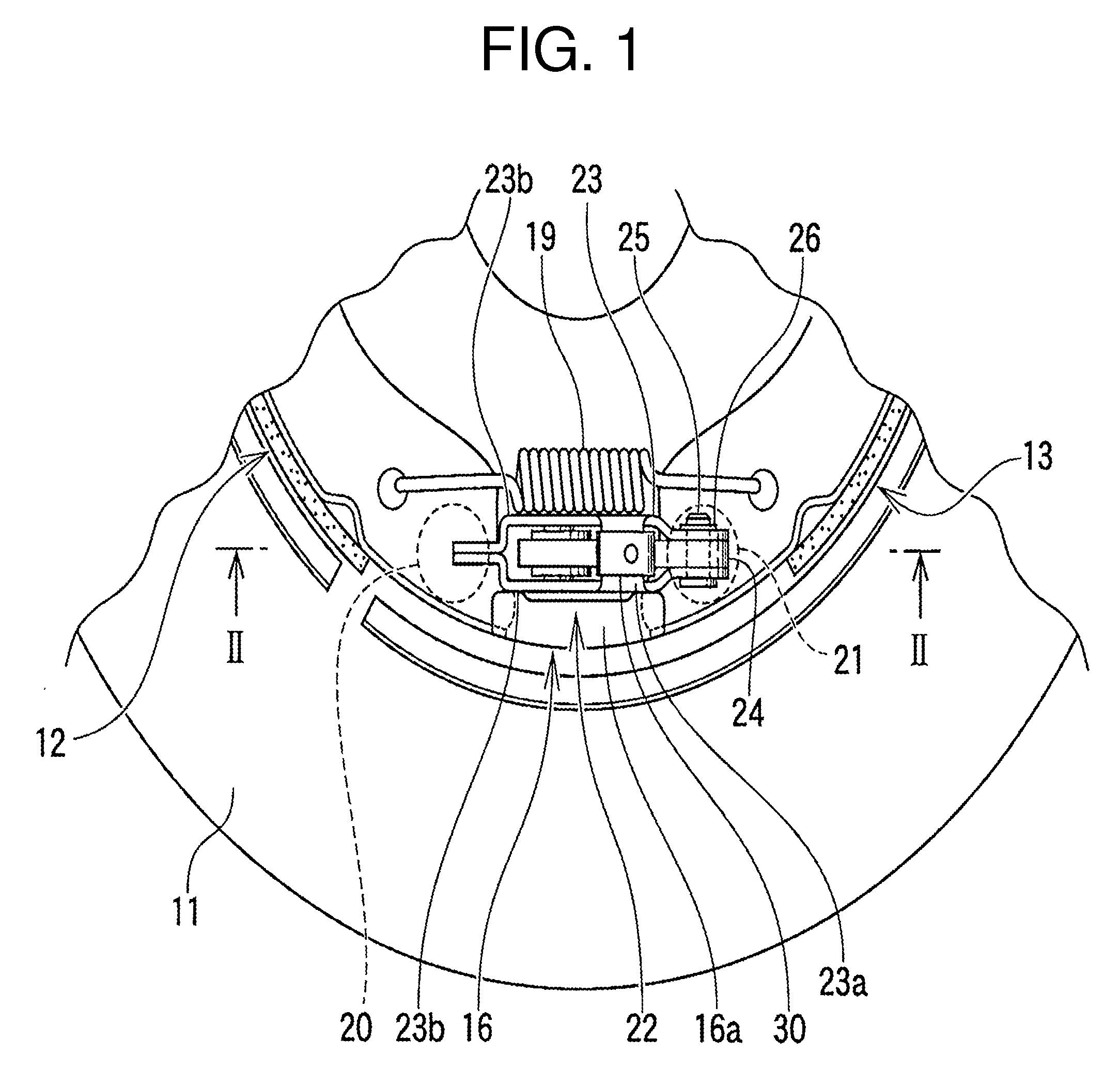
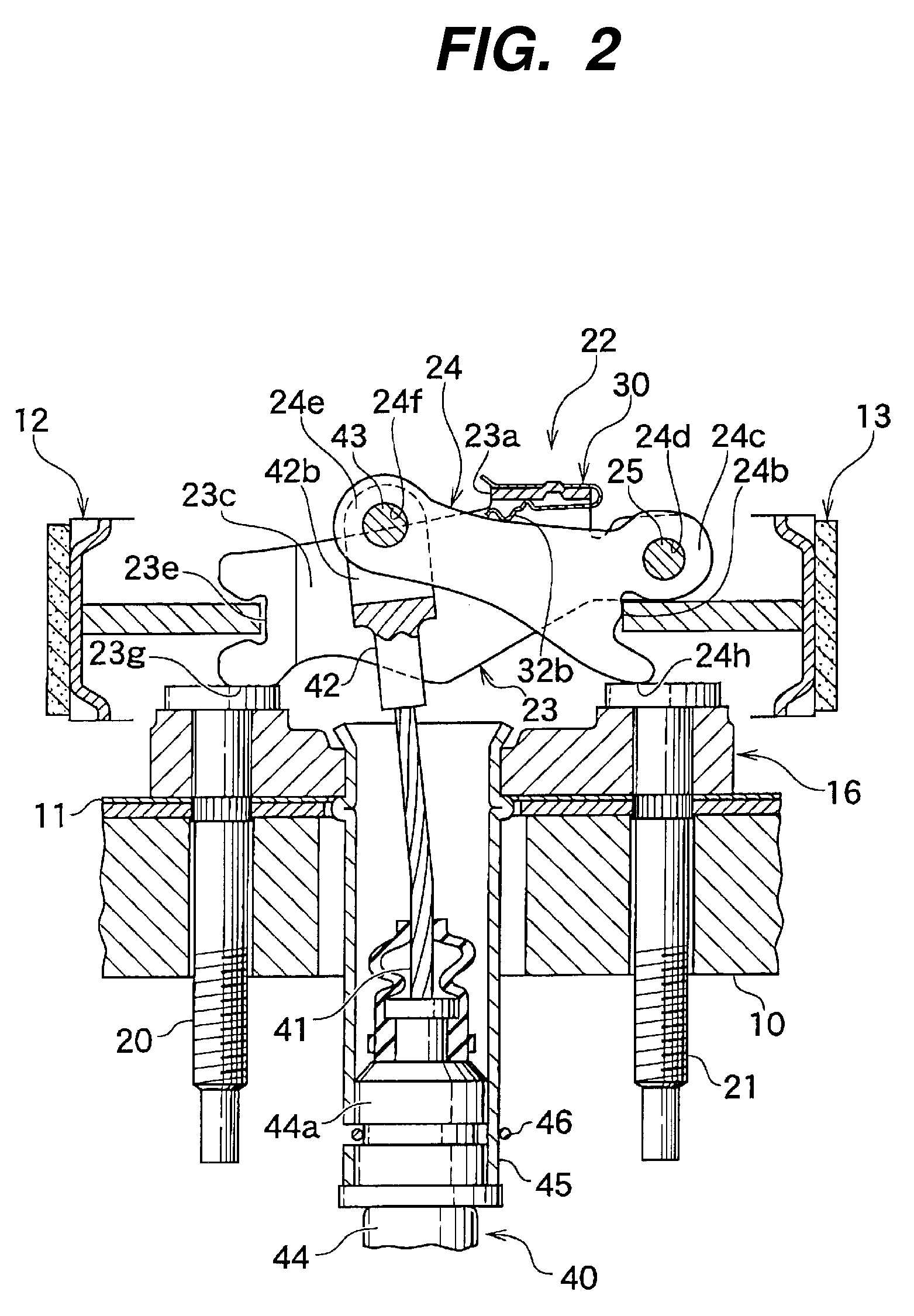
[0029]In the following sections, a mechanical brake actuator relating to a first embodiment of the present invention will be explained.

[0030]FIG. 1 is a plan view of an example of the drum brake device with the mechanical brake actuator, FIG. 2 is a cross-sectional view of FIG. 1, and FIG. 3 is an exploded perspective view of the above-described mechanical brake actuator.

[0031]The first embodiment will be explained with reference to the drawings.

[0032]A pair of brake shoes 12 and 13 are movably mounted, via a shoe hold mechanism (not shown in the figures), on a back plate 11 which is fixed on a stationary portion 10 of a vehicle, and one pair of facing ends of the brake shoes 12 and 13 are supported by raised portion 16a of a later described anchor 16 while the other pair of facing ends thereof are connected via a joint member. A pair of shoe return springs (where only one shoe return spring 19 of the two shoe return springs appears in the figure), extended between both brake shoes ...


PUM


Abstract

To provide the mechanical brake actuator enabling to downsize the device and to reduce the manufacturing costs of the parts. The mechanical brake actuator comprises the strut (23) which engages with one brake shoe (12) and has two facing plates (23b) with a strut-bridge (23a) connecting therebetween and the plate-like brake lever (24) which engages with the other brake shoe (13). The brake lever (24) is retained in the space (23c) between the facing strut plates and is pivotally supported on the strut (23), and the inner cable (41) of the brake cable (40) connected to the free end (24e) of the brake lever (24) via the connecting pin (43). The mechanical brake actuator which is operated by pulling the inner cable (41) comprises the clip (70), which rotatably attaches to the strut-bridge (23a) and restricts the rotation of the brake lever (24) in the cable releasing direction.

Description

REFERENCE TO PRIOR APPLICATION[0001]This application is a continuation-in-part of prior application Ser. No. 11 / 463,311, filed on Aug. 9, 2006, which claims priority benefit of the original applications numbers JP2005-230683 filed on Aug. 9, 2005 and JP2005-317040 filed on Oct. 31, 2005.BACKGROUND OF THE INVENTION[0002]1. Field of the Invention[0003]The invention relates to a mechanical brake actuator providing an easy preventive measure for brake cable disengagement.[0004]2. Description of the Related Art[0005]A brake actuator of this type is comprised of a plate-like brake lever, a strut pivotally retained the brake lever therein, and a pivotal pin, wherein the mechanical actuator is positioned between a pair of brake shoes, and the brake lever and the strut relatively rotates as operating, i.e., pulling a brake cable connected to the brake lever, while spreading the brake lever and the strut apart from each other in an opposite direction.[0006]After engaging the brake cable with ...

Claims


Application Information

Patent Timeline
IPC IPC(8): F16D65/14
CPCF16D65/22F16D2125/68F16D2125/62F16D2121/14
Inventor TAKAI, HIDEYUKI
Owner AH BRAKE CO LTD
Why Eureka
Try Eureka