Fabric clip applicable to burred fabric

A burr and fabric technology, applied in the direction of fabric elongation, textile and papermaking, fabric surface trimming, etc., can solve the problems of non-straight weft and can not be cut, and achieve the effect of increasing the amount of selvedge and improving economic benefits.

Pending Publication Date: 2018-08-21
JIANGSU LITTLE SUN TECH DEV CO LTD
View PDF3 Cites 0 Cited by
  • Summary
  • Abstract
  • Description
  • Claims
  • Application Information

AI Technical Summary

Problems solved by technology

[0002] Nowadays, in order to save fabric and improve the utilization rate of raw materials, many manufacturers move the process of cutting raw edges to the end, and some even need to use raw edges, which cannot be cut
However, when the fabric with large burrs is being stentered, the burrs will get stuck on the rollers. The rollers cannot fall to the bottom and the clips cannot fall to the bottom. The situation that the clips are not tightly clamped or clipped off is reflected in the fabric with crescent edges, wavy edges, or warp and weft threads that are not straight

Method used


Image

  • Fabric clip applicable to burred fabric
  • Fabric clip applicable to burred fabric

Examples


Embodiment 1

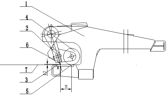
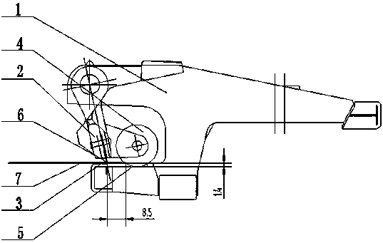
[0012] Embodiment 1: as figure 1 , 2 Shown is a cloth clip suitable for raw-edged fabrics, including a clip main body 1, a clip body 2, and a blade plate surface 3, a roller 4 is arranged at the rear of the clip body 2, a blade 6 is clamped in the clip body 2, and the blade The knife edge of 6 is opposite to the knife edge plate surface 3, the notch 5 corresponding to the roller 4 is opened on the knife edge plate surface 3, and the raw edge cloth 7 is placed on the knife edge plate surface 3, and the rough edge area of ​​the raw edge fabric 7 is located between the roller 4 and the notch 5 Between them, the raw edge cloth 7 moves along the knife-edge plate 3 in a direction away from the notch 5, and the roller 4 moves toward the notch 5 until it falls into the notch 5. When the blade 6 is clamped to the non-burr region of the raw edge cloth 7, The roller 4 does not intersect the burr area of ​​the burr fabric 7. When the roller 4 is tangent to the knife-edge panel 3, the dis...

Embodiment 2

[0013] Embodiment 2: With reference to Example 1, when the roller 4 is tangent to the knife edge plate surface 3, the distance between the knife edge and the knife edge plate surface 3 is 0.7 mm, and when the knife edge contacts the knife edge plate surface 3, the roller 4 falls into the depth of the notch 5 is 1.4mm, and the outer diameter of the roller 4 is φ17m.

Embodiment 3

[0014] Embodiment 3: With reference to Example 1, when the roller 4 is tangent to the knife edge plate surface 3, the distance between the knife edge and the knife edge plate surface 3 is 0.9 mm, and when the knife edge contacts the knife edge plate surface 3, the roller 4 falls into the depth of the notch 5 is 1.6mm, and the outer diameter of the roller 4 is φ19m.


PUM


Abstract

The invention provides a fabric clip applicable to burred fabric. The fabric clip comprises a fabric clip main body, a knife clip body and a blade edge plate surface, wherein a roller wheel is arranged on the back part of the knife clip body; a blade is clipped inside the knife clip body; the blade edge of the blade is opposite to the blade edge plate surface; a notch corresponding to the roller wheel is formed in the blade edge plate surface; the burred fabric is placed on the blade edge plate surface; a burred area of the burred fabric is positioned between the roller wheel and the notch; the burred fabric moves along the blade edge plate surface and away from the notch; the roller wheel moves towards the notch until the roller wheel falls into the notch; when the blade clips a non-burred area of the burred fabric, the burred area of the burred fabric is not clipped between the roller wheel and the notch. The roller wheel is not clipped by the burred area, so that crescent edges, wavy edges or unstraight warps and wefts are not generated on the fabric; the edge clipping amount is increased, so that no matter for the burred fabric or ordinary fabric, the situation of clip droppingor a loose knife clip is reduced, and thus the economic benefits are greatly improved.

Description

technical field [0001] The invention relates to an accessory of a setting machine in dyeing and finishing production, in particular to a cloth clip suitable for raw-edged cloth. Background technique [0002] Nowadays, in order to save fabric and improve the utilization rate of raw materials, many manufacturers move the process of cutting raw edges to the end, and some even need to use raw edges and cannot be cut. However, when the fabric with large burrs is being stentered, the burrs will get stuck on the rollers. The rollers cannot fall to the bottom and the clips cannot fall to the bottom. The situation that the clips are not clamped tightly or come off is reflected in the fabric with crescent edges, wavy edges, or warp and weft threads that are not straight. Contents of the invention [0003] Purpose of the invention: The purpose of the present invention is to address the deficiencies of the prior art and provide a cloth clip suitable for fabrics with raw edges. The e...

Claims


Application Information

Patent Timeline
Patent Type & Authority Applications(China)
IPC IPC(8): D06C3/04
CPCD06C3/04
Inventor 张才南张盛周燕钱祖勤
Owner JIANGSU LITTLE SUN TECH DEV CO LTD
Why Eureka
Try Eureka