On-line permanent gas filling monitoring method and system

A monitoring system and permanent technology, applied in container filling method, container discharge method, gas/liquid distribution and storage, etc., can solve the problems of complex measuring device, inability to detect the temperature of gas tank in real time, and troublesome measuring method, etc. Conducive to centralized management

Inactive Publication Date: 2014-02-05
福建启胜博通电子科技有限公司
View PDF5 Cites 0 Cited by
  • Summary
  • Abstract
  • Description
  • Claims
  • Application Information

AI Technical Summary

Problems solved by technology

[0002] During the filling process of the existing gas tank, it is impossible to detect the temperature inside the gas tank in real time, or there are problems such as troublesome measurement methods and complicated measurement devices
If the temperature inside the gas tank cannot be detected in real time, there is no way to fill a sufficient amount of gas within a safe range. There will be "half bottles" and even "empty bottles" that have been leaked, and explosions may occur due to overfilling
[0003] There are three important issues in the permanent gas filling process: one is the filling safety problem, how to find the problem in time when the combustible gas and the combustion-supporting gas are mixed; the other is the filling quality problem, the customer bought our product, we It is necessary to be responsible for the product. Sometimes some customers hand in "empty bottles" and get "half bottles" that are underfilled, or even "empty bottles" that are missing. The third is the problem of filling pieces. How many gas cylinders are filled by employees in a month, and how many gas cylinders are filled in each shift, these data are simple but cumbersome, but these are very important for future enterprise management

Method used


Image

  • On-line permanent gas filling monitoring method and system
  • On-line permanent gas filling monitoring method and system

Examples


Embodiment Construction

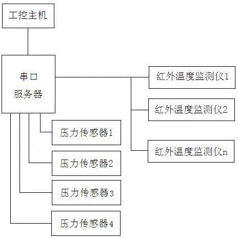
[0016] The present invention provides an on-line monitoring method for permanent gas filling, and provides an industrial control host connected to an industrial data acquisition communication server, the industrial data acquisition communication server and a plurality of infrared temperature monitors and a plurality of pressure sensors Networking is carried out, and the plurality of infrared temperature monitors are respectively arranged in the middle of the gas tank, and the plurality of pressure sensors are respectively arranged on the gas filling pipeline, thereby collecting the pressure and temperature of the gas tank, and then controlling the filling process of the gas tank Manage and control.

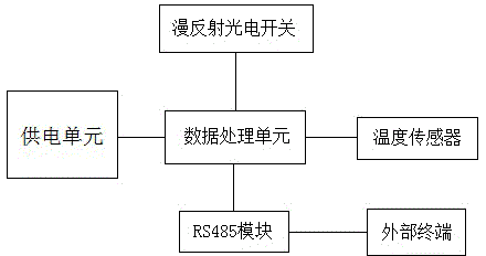
[0017] The infrared temperature monitor includes a data processing unit, and the data processing unit is connected with an infrared temperature acquisition unit, a diffuse reflection photoelectric switch and an RS485 module, and the RS485 module is used for communicating with an ex...


PUM


Abstract

The invention relates to an on-line permanent gas filling monitoring method which is characterized in that an industrial control host is provided and is connected with an industrial data acquisition and communication server; the industrial data acquisition and communication server is networked with a plurality of infrared temperature monitors and a plurality of pressure sensors; the infrared temperature monitors are respectively arranged on the middle part of a gas tank, and the pressure sensors are respectively arranged on a gas filling pipeline, so that the pressure and the temperature of the gas tank can be acquired, and a filling process of the gas tank can be managed and controlled. According to the on-line permanent gas filling monitoring method, infrared detection on temperatures is adopted, so that a user does not need to touch a detected object, and the on-line permanent gas filling monitoring method is suitable for measuring and monitoring of gas industry; an existing target is inducted in real time through a diffuse reflection photoelectric switch, so that a function of counting filled gas bottles is realized, and the temperature of the target can be automatically monitored; furthermore, the industrial data acquisition and communication server is used for sending acquired temperature information and pressure information to the industrial control host, so that concentrative management is facilitated.

Description

technical field [0001] The invention relates to the field of gas tank filling detection, in particular to a permanent gas filling online monitoring method and system. Background technique [0002] During the filling process of the existing gas tank, the temperature in the gas tank cannot be detected in real time, or there are problems such as troublesome measurement methods and complicated measurement devices. If the temperature inside the gas tank cannot be detected in real time, there will be no way to fill a sufficient amount of gas within a safe range. There will be "half bottles" and even "empty bottles" that are not filled, and explosions may occur due to overfilling. [0003] There are three important issues in the permanent gas filling process: one is the filling safety problem, how to find the problem in time when the combustible gas and the combustion-supporting gas are mixed; the other is the filling quality problem, the customer bought our product, we It is nece...

Claims


Application Information

Patent Timeline
IPC IPC(8): F17C13/02G01D21/02
Inventor 范贵茂
Owner 福建启胜博通电子科技有限公司
Why Eureka
Try Eureka