Check patentability & draft patents in minutes with Patsnap Eureka AI!

Card connector structure

A card connector, electronic card technology, applied in the direction of connection, connecting device parts, electrical components, etc., can solve the problems of low production capacity, low durability, and difficult quality assurance.

Inactive Publication Date: 2014-02-05
连展科技电子(昆山)有限公司
View PDF6 Cites 0 Cited by
  • Summary
  • Abstract
  • Description
  • Claims
  • Application Information

AI Technical Summary

Problems solved by technology

However, when the card connector is connected, capacitance is generated when the two conductors are close to each other. In this high-frequency environment, the impedance reduction caused by this capacitance effect cannot be ignored.
Therefore, impedance matching must be carried out so that the signal will not be distorted. Existing card connectors have the problem of high-frequency electrical impedance matching
[0007] 2. The insulating body system of the existing card connector is individually assembled on the insulating base body. When assembled, the insulating body is easily broken or the strength is insufficient. Moreover, the insulating body must be assembled manually, and its production capacity is low. , the quality is difficult to guarantee
[0008] 3. The terminal size of the existing card connector is small, and it is difficult to ensure the insertion and withdrawal force when the electronic card is inserted due to the elasticity of the terminal itself
[0009] 4. The insulating seat body of the existing card connector has insufficient structural strength and low durability

Method used


Image

  • Card connector structure
  • Card connector structure
  • Card connector structure

Examples


Embodiment Construction

[0031] In order to achieve the above objectives and effects, the features and functions of the preferred embodiments of the present invention are described in detail as follows.

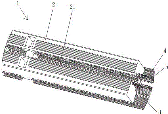
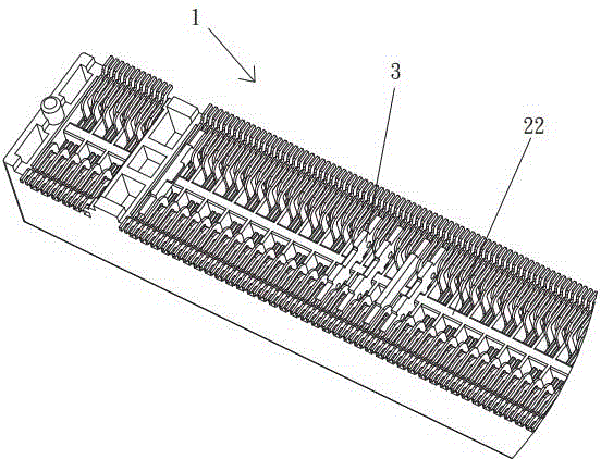
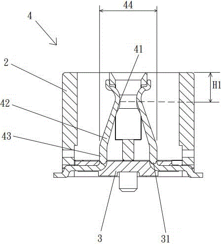
[0032] see figure 1 , figure 2 and Figure 5 As shown, it is a three-dimensional view of a preferred embodiment of the present invention Figure 1 , two and partial hint Figure 1 , it can be clearly seen from the figure that the present invention is a card connector 1 structure, and the card connector 1 at least includes: an insulating base body 2, an insulating body 3, and a first terminal group 4 and a second terminal group 5.

[0033] The insulating base 2 includes a card slot 21 for accommodating a predetermined electronic card (not shown in the figure). In this embodiment, ribs 22 are arranged on the bottom of the insulating base 2, and the electronic card is a display card.

[0034] The insulating bodies 3 are arranged in the insulating base 2 and include two terminal slots 31 .

[003...


PUM


Abstract

A card connector structure at least comprises an insulation seat body, an insulation body, a first terminal group and a second group, wherein the insulation seat body comprises a card channel to store an electric card to be stored; the insulation body is arranged inside the insulation seat body and is consisted of two terminal channels; the first terminal group and the second terminal group are set in the two terminal channels of the insulation body; the first terminal group and the second terminal group have a first contact point and a second contact point to contact the electric card respectively; the first contact point is higher than the second contact point. Because of the structure above, high-frequency electrical impedance can be avoided and the card connector is more stable.

Description

technical field [0001] The invention relates to a card connector structure, in particular to a card connector structure which can avoid high-frequency electrical impedance and make the card connector more stable. Background technique [0002] With the advancement of technology, various electronic devices are flooding our lives, and in order to enable the electronic devices to achieve the effect of signal transmission, various connectors have become necessary components. [0003] Among them, the card connector is widely used on the motherboard of the personal computer to connect various electronic cards such as display cards, sound cards or network cards to achieve specific functions. The card connector includes: an insulating seat body , insulating body and terminal set. The insulating seat body includes a card slot for accommodating a preset electronic card; the insulating body is arranged in the insulating seat body and includes a terminal groove; and the terminal is arra...

Claims


Application Information

Patent Timeline
Patent Type & Authority Applications(China)
IPC IPC(8): H01R13/6473H01R13/6474H01R12/71
CPCH01R12/716H01R12/721H01R13/6473
Inventor 蔡侑伦侯斌元李国清
Owner 连展科技电子(昆山)有限公司
Features
  • R&D
  • Intellectual Property
  • Life Sciences
  • Materials
  • Tech Scout
  • Unparalleled Data Quality
  • Higher Quality Content
  • 60% Fewer Hallucinations
Learn More