Electrical connector with improved contacts

a technology of electrical connectors and contacts, applied in the direction of electrical devices, electrical discharge lamps, coupling device connections, etc., can solve the problems of unsteady current transmission of the terminals of traditional i/o connectors, and cannot reach the level of 5

Active Publication Date: 2015-06-11
FOXCONN INTERCONNECT TECHNOLOGY LIMITED
View PDF14 Cites 9 Cited by
  • Summary
  • Abstract
  • Description
  • Claims
  • Application Information

AI Technical Summary

Problems solved by technology

In this case, the current transmitting by the terminals can not achieve to 5 A and th

Method used


Image

  • Electrical connector with improved contacts
  • Electrical connector with improved contacts
  • Electrical connector with improved contacts

Examples


Embodiment Construction

[0014]Reference will now be made to the drawing figures to describe the present invention in detail.

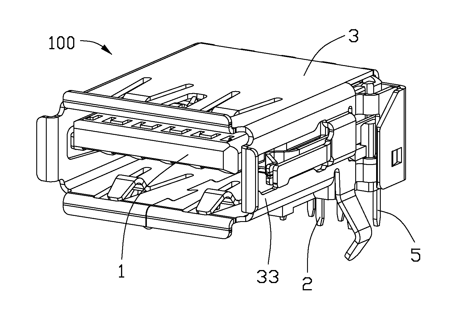
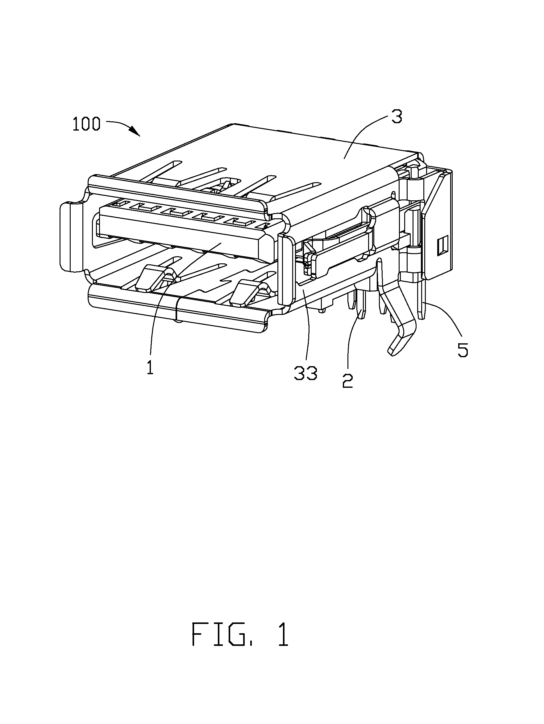
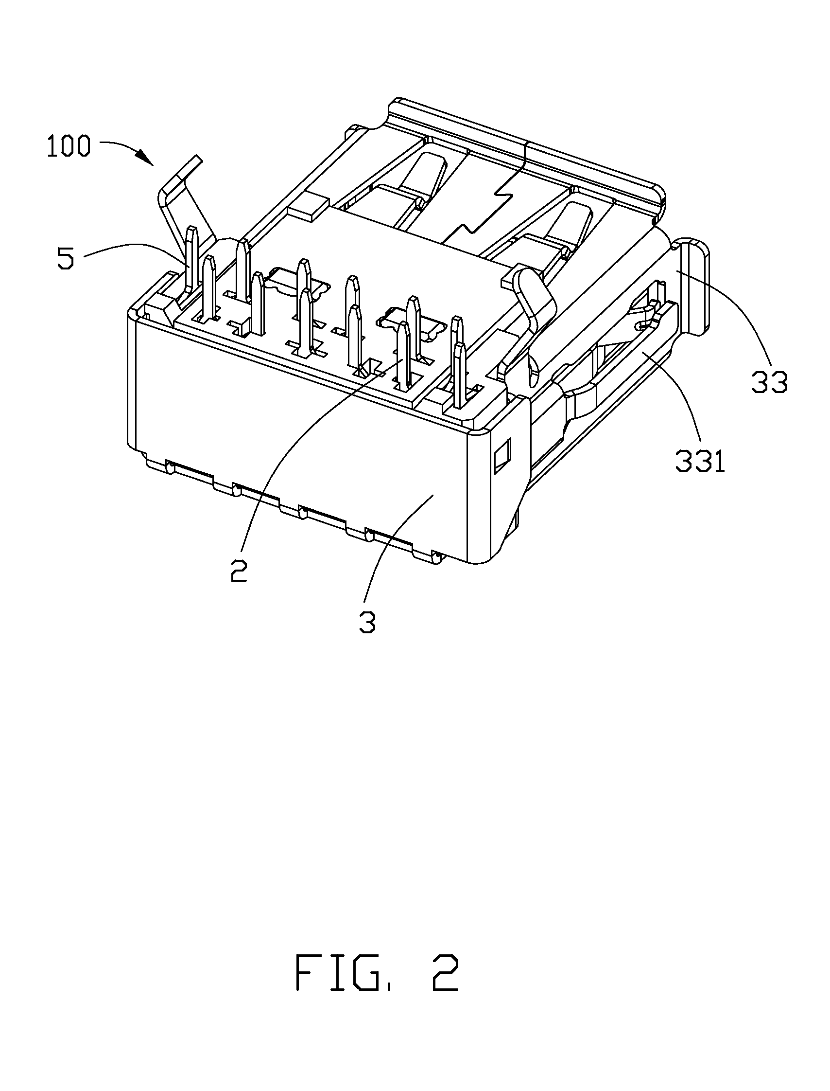
[0015]FIGS. 1-6 show an electrical connector 100 used for being mounted onto an external printed circuit board. The electrical connector 100 includes an insulative housing 1, a plurality of terminals 2 received in the insulative housing 1, a shell 3 covering the insulative housing 1, a plurality of detecting terminals 5, and a terminal block 6.

[0016]FIGS. 3-5 show the insulative housing 1 including a base portion 11 and a tongue plate 12 extending from the base portion 11 forwardly. The base portion 11 includes an upper surface 111, a lower surface 112, two lateral portions 113, a front surface 114, and a rear surface 115. The base portion 11 includes two receiving cavities 1130 recessed from the upper surface 111 downwardly, and the two receiving cavities 1130 are defined at two side of the base portion 11. The base portion 11 also includes a receiving space 1150 recessed from the re...


PUM


Abstract

An electrical connector (100) includes an insulative housing (1), a plurality of terminals (2) received in the insulative housing, and a shell (3). The insulative housing includes a base portion (11) and a tongue plate (12) extending from the base portion forwardly. The tongue plate includes a mating face (13) and a supporting face (14) opposite to the mating face. The terminals (22) include a pair of signal terminals defined in the supporting face, a grounding terminal, and a power terminal. The pair of signal terminals are defined between the grounding terminal and the power terminal. Each of the signal terminals, the grounding terminal, and the power terminal has a thickness greater than 0.2 mm. The power terminal is made of nickel and copper.

Description

BACKGROUND OF THE INVENTION[0001]1. Field of the Invention[0002]The present invention relates to an electrical connector, and more particularly to an electrical connector having a plurality of terminals with steadily transmitting current.[0003]2. Description of Prior Arts[0004]Traditional I / O connector includes a plurality of terminals used for transferring current or signal, and the terminals are made of brass or phosphor copper. The terminals can steadily transfer current of 1.8 A, but when the terminals transfer current of 5 A, temperature of the terminals rise fast and impedance of the terminals increase. In this case, the current transmitting by the terminals can not achieve to 5 A and the current transmission of the terminals of the traditional I / O connector is unsteady.[0005]An electrical connector having a plurality of terminals with steadily current transmission is desired.SUMMARY OF THE INVENTION[0006]An electrical connector includes an insulative housing, a plurality of t...

Claims


Application Information

Patent Timeline
IPC IPC(8): H01R24/62H01R13/03
CPCH01R24/62H01R2107/00H01R13/03H01R12/724H01R13/6594
Inventor YU, CHUN-MING
Owner FOXCONN INTERCONNECT TECHNOLOGY LIMITED
Why Eureka
Try Eureka