Battery for vehicle, and method for producing battery

A battery and vehicle technology, applied in the field of batteries used in vehicles and used in the manufacture of batteries, can solve the problems of high consumption and achieve the effect of low consumption and light weight

Active Publication Date: 2014-02-05
AUDI AG
View PDF6 Cites 9 Cited by
  • Summary
  • Abstract
  • Description
  • Claims
  • Application Information

AI Technical Summary

Problems solved by technology

[0005] In the batteries disclosed in these prior art, it is relatively expensive to bring the cooling device into good heat-conducting contact with the battery cells.

Method used


Image

  • Battery for vehicle, and method for producing battery
  • Battery for vehicle, and method for producing battery
  • Battery for vehicle, and method for producing battery

Examples


Embodiment Construction

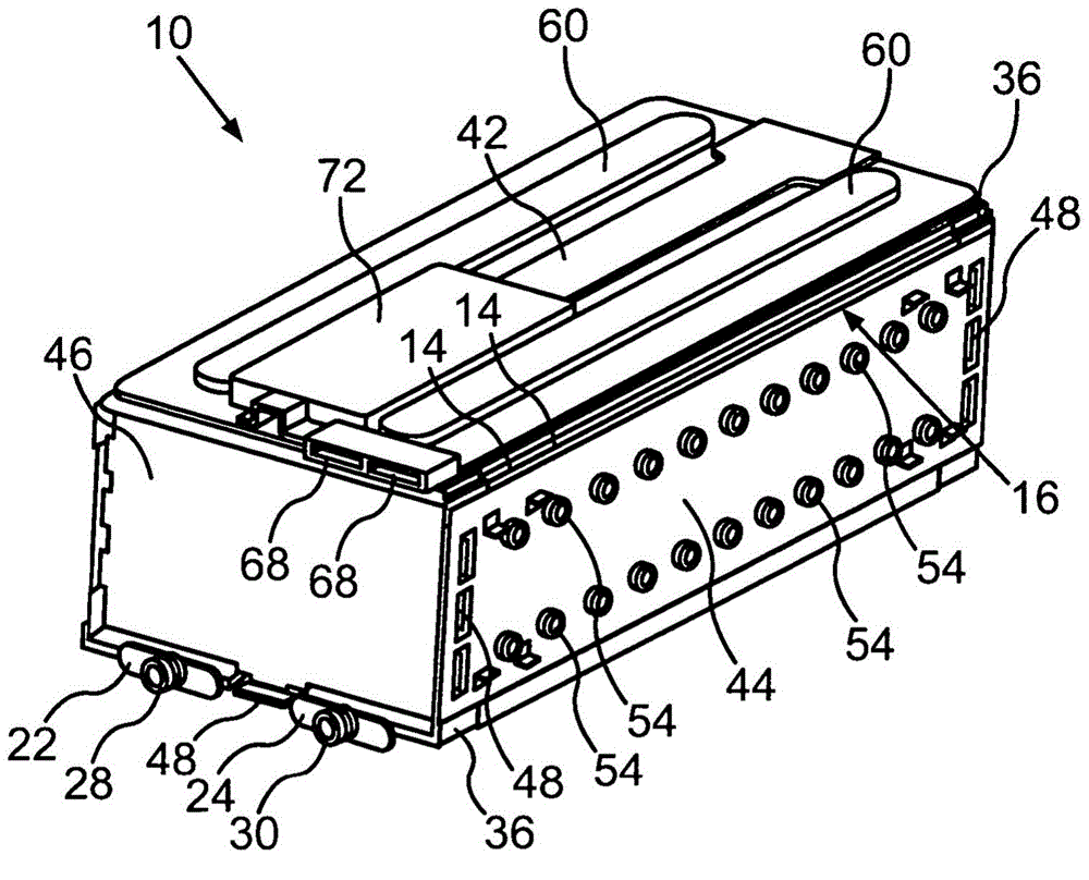
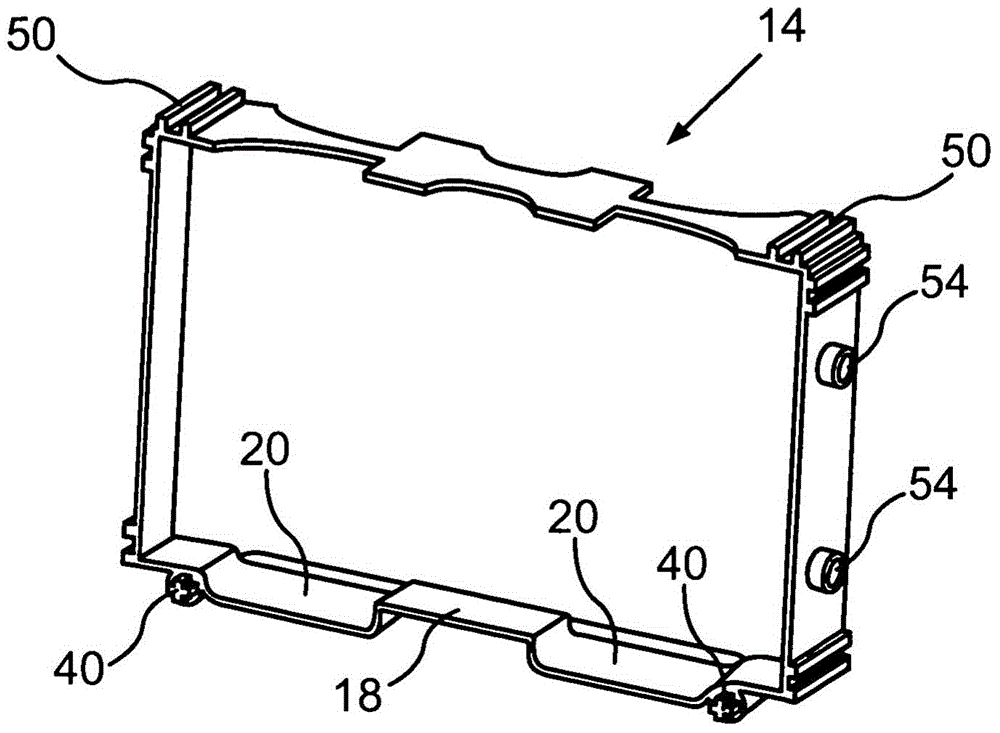
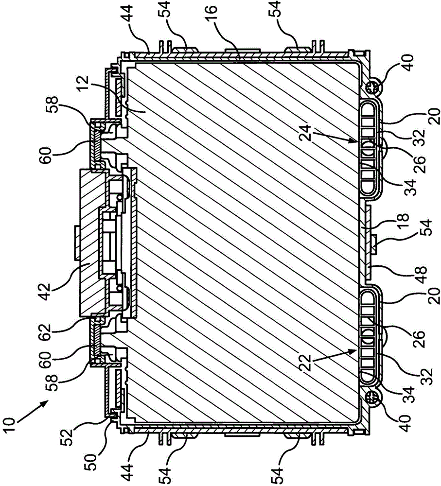
[0029] figure 1 The illustrated battery 10 for a vehicle is designed, for example, as a lithium-ion battery. The battery 10 has a plurality of battery cells 12 which are electrically insulated from one another by separators 14 made of plastic, also called separators (see Figure 6 ). The aforementioned prismatic battery cells 12 form a stack.

[0030] The separators 14 connected to each other by an adhesive constitute the side walls 16 and the bottom plate 18 of the casing of the battery 10 (see figure 2 ), in which a stack of battery cells 12 is accommodated. In the area of ​​the housing floor 18 formed by the partition 14, two channels 20 are formed by the partition 14 (see figure 2 ), which accommodates the two profile parts 22, 24 of the cooling device (see figure 1 ).

[0031] The profile parts 22, 24 are designed as flat tubes through which the coolant can flow, and in the flat tubes, cooling fins 26 form a plurality of cooling passages parallel to each other (se...


PUM


Abstract

The invention relates to a battery (10) for a vehicle. Said battery comprises a plurality of battery cells (12), which are arranged in a housing (16, 18, 20) of the battery (10), and also a cooling device (22, 24) for dissipating heat from the battery cells (12). A material (32), which takes up a first volume in a basic state and takes up a volume which is greater than the first volume in an expanded state, is introduced between the housing (20) and the cooling device (22, 24). The cooling device (22, 24) is pressed against the battery cells (12) by the material (32) which has changed over to its expanded state. The invention also relates to a method for producing a battery (10) of this kind.

Description

technical field [0001] The invention relates to a battery for a vehicle, in which a plurality of battery cells are arranged in a battery housing. The battery has a cooling device for removing heat from the battery cells. The invention also relates to a method for producing such a battery. Background technique [0002] DE 10 2007 021 293 A1 describes a battery for an electric vehicle, a fuel cell vehicle or a hybrid vehicle. The individual battery cells combined to form a battery pack are surrounded outwardly by a common plastic housing. The housing has a container that is open on one side and a top cover that closes the container, both of which are made by die-casting. In order to ensure that the battery cells are fixed in the housing in a fixed position and without gaps, positioning flanges are provided on the bottom and the top cover of the housing, and the regions of the positioning flanges have different elasticity. The softer regions of the positioning flanges allow...

Claims


Application Information

Patent Timeline
Patent Type & Authority Applications(China)
IPC IPC(8): H01M10/613H01M10/6554H01M10/6556H01M10/625
CPCY02E60/12H01M10/5075H01M10/5057H01M10/5016H01M10/5004H01M10/5032H01M10/5053H01M10/049H01M10/613H01M10/647H01M10/6554H01M10/6556H01M10/6567H01M10/625Y02E60/10Y10T29/49108Y02P70/50
Inventor H·费斯A·特拉克R·迈施
Owner AUDI AG
Why Eureka
Try Eureka