Microwave heating device

A microwave heating device and microwave technology, applied in microwave heating, electric heating device, electric/magnetic/electromagnetic heating, etc., can solve problems such as inability to make models

Inactive Publication Date: 2014-02-05
PANASONIC CORP
View PDF5 Cites 14 Cited by
  • Summary
  • Abstract
  • Description
  • Claims
  • Application Information

AI Technical Summary

Problems solved by technology

[0006] However, there is a problem in the above-mentioned conventional microwave heatin

Method used


Image

  • Microwave heating device
  • Microwave heating device
  • Microwave heating device

Examples


Embodiment approach 1

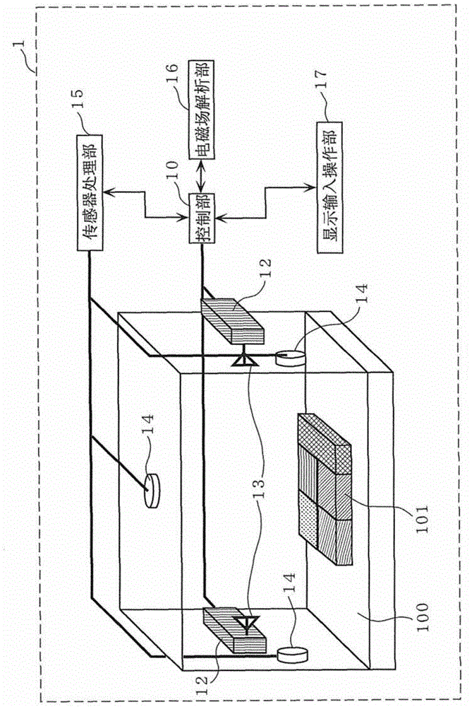
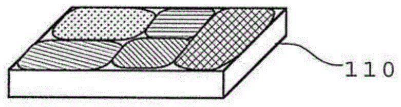
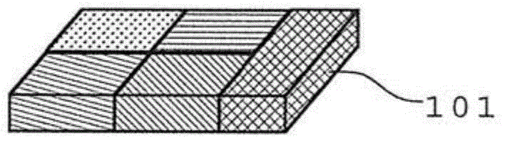
[0066] figure 1 The structure of the microwave heating apparatus 1 in Embodiment 1 is shown. figure 2 An object to be heated 110 to be heated in the microwave heating device in Embodiment 1 is schematically shown. Figure 3A as well as Figure 3B A block model modeling the object to be heated is shown.

[0067] figure 1 The shown microwave heating device 1 heats an object to be heated 110 to be heated according to a heating profile. More specifically, microwave heating device 1 heats object 110 by irradiating microwaves in accordance with a heating profile derived from electromagnetic field analysis.

[0068] Here, the object to be heated 110 is the object to be heated when the microwave heating device 1 is actually heating, such as figure 2 As shown, there are sites (multiple sites) with different material elements. For example, when the object to be heated 110 is a lunch box composed of rice and various side dishes, the rice and side dishes correspond to parts with d...

Deformed example 1

[0102] In this modified example, another example of a block model configured instead of the object to be heated 110 will be described.

[0103] Figure 5 A block model 201 of the object to be heated 110 in Modification 1 of the present embodiment is shown.

[0104] Figure 5 The block model 201 shown differs from the block model 101 according to Embodiment 1 in that in order to emphasize the outlines of the sub-blocks 201 a - 201 e , lines for emphasizing the outlines are drawn on the outlines. That is, the size, shape, etc. of the sub-blocks of the block model 201 are the same as Figure 3A The block model 101 shown is the same, and the parts constituting the respective sides of the sub-blocks 201a-201e are drawn with thick lines to emphasize the outline of the sub-blocks 201a-201e. Here, the width of the line is, for example, 5 mm or more.

[0105] In this modified example, the flow up to the heating treatment of the object to be heated 110 is basically the same as that ...

Deformed example 2

[0112] In this modification, an example of a block model different from Modification 1 will be described. Specifically, a mark showing corresponding information is given to the surface of each sub-block constituting the block model, and this case will be described below as an example. The sensor 14 detects information by recognizing the mark. Hereinafter, as an example, the symbol will be described as a barcode.

[0113] Figure 6A as well as Figure 6B A block model of the object to be heated 110 in Modification 2 of the present embodiment is shown.

[0114] Figure 6A The block model 301 shown is different from the block model 101 according to Embodiment 1 in that a barcode (one-dimensional barcode) is provided on the surface of the sub-blocks 301a-301e. same, Figure 6B The block model 302 shown is different from the block model 101 according to Embodiment 1 in that a two-dimensional barcode is provided on the surface of the sub-blocks 301a-301e.

[0115]More specifi...


PUM


Abstract

A microwave heating device pertaining to one embodiment of the present invention is provided with: a plurality of antennas (13) for irradiating microwaves inside a heating chamber (100) that contains a heated object (110) having a plurality of regions; a sensor (14) for detecting information indicating characteristics of the individual regions from a block model (101) to which the information has been imparted; a display and input operating part (17) through which a condition of heating the heated object (110) is inputted; an electromagnetic field analyzing part (16) for deriving by electromagnetic field analysis a heating profile including a condition for irradiating microwaves at the heated object (110), the derivation being performed on the basis of the information detected by the sensor (14) and the heating condition inputted into the display and input operating part (17); and a control part (10) for controlling, on the basis of the derived heating profile, the action of microwaves irradiated by the antennas (13).

Description

technical field [0001] The present invention relates to a microwave heating device, and more particularly to a microwave heating device for heating an object to be heated as a heating target according to a heating outline. Background technique [0002] In a conventionally known microwave heating device, represented by a microwave oven, an infrared sensor is used to measure the surface temperature of an object to be heated, and control is performed until the object is heated to a desired temperature. Furthermore, there is also disclosed a microwave heating device that controls heating to a desired temperature by directly measuring the shape of an object to be heated with a sensor such as a camera (for example, Patent Document 1). [0003] (Prior art literature) [0004] (patent documents) [0005] Patent Document 1 Japanese Patent Laid-Open No. 2003-232527 [0006] However, in the conventional microwave heating apparatus described above, there is a problem that an accurate...

Claims


Application Information

Patent Timeline
IPC IPC(8): H05B6/68
CPCH05B6/70H05B6/6447H05B6/72H05B6/705H05B6/645
Inventor 池田光岩田基良神山智英
Owner PANASONIC CORP
Why Eureka
Try Eureka