A self-resetting triple steel tube constrained buckling brace and its manufacturing process

A restrained buckling and self-resetting technology, which is applied to building components, earthquake resistance, etc., can solve the problems of limited cross-sectional size of connecting sections, dissipation of seismic energy, and easy corrosion, so as to reduce the risk of bending instability and improve transmission efficiency. Power reliability, broad application prospects

Inactive Publication Date: 2015-10-28
NANJING TECH UNIV
View PDF6 Cites 0 Cited by
  • Summary
  • Abstract
  • Description
  • Claims
  • Application Information

AI Technical Summary

Problems solved by technology

[0003] The energy consumption of existing self-resetting support components is mainly frictional energy consumption, and its curve is relatively full. But there are two main limitations: first, the friction force depends on the pre-tightening force of the bolts, and when the bolts are loosened, the pre-tightening force decreases , it will affect the friction force and cannot dissipate the seismic energy normally
[0006] 2. The ends of the inner and outer casings are prone to damage
Various factors make the end particularly weak
[0007] 3. The components are poorly sealed and prone to corrosion
[0008] 4. The connecting section is too long
And due to its structural characteristics, the cross-sectional size of the connecting section is limited, and it is prone to instability and damage, so the force transmission of the connecting section is not reliable

Method used


Image

  • A self-resetting triple steel tube constrained buckling brace and its manufacturing process
  • A self-resetting triple steel tube constrained buckling brace and its manufacturing process
  • A self-resetting triple steel tube constrained buckling brace and its manufacturing process

Examples


Embodiment Construction

[0031] The present invention will be further described below in conjunction with the accompanying drawings and specific embodiments.

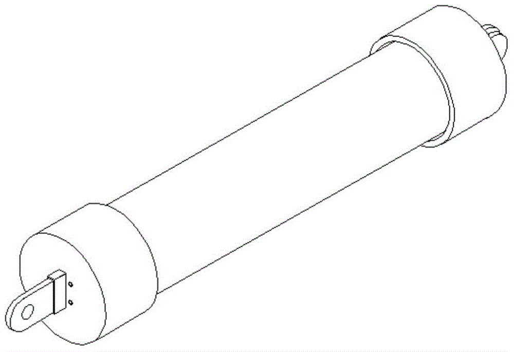
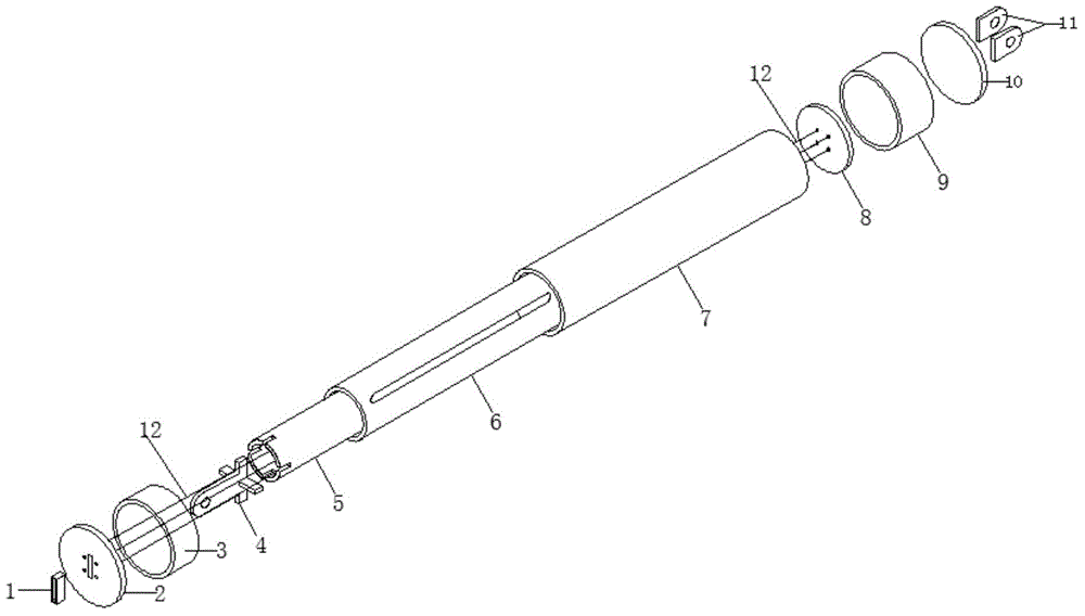
[0032] Such as Figure 1-4 Shown: a self-resetting triple steel pipe constrained buckling support, including a rectangular pipe 1, a first end plate 2, a first round steel pipe section 3, a first connecting plate 4, an inner restraint steel pipe 5, an intermediate energy-dissipating pipe 6, and an outer restraint steel pipe 7. The second end plate 8, the second round steel pipe section 9, the circular plate 10, the second connecting plate 11 and the steel strand 12;

[0033] The first end plate 2 is provided with a rectangular hole, and the rectangular hole is provided with a rectangular tube 1, and the first end plate 2 is welded into a whole with the first round steel pipe section 3 and the rectangular tube 1 to form a first end casing ;

[0034] The second connecting plate 11 is welded to the circular plate 10, and the circular plate 10 is...


PUM


Abstract

The invention discloses a self-resetting triple-steel-tube buckling-restrained brace and a manufacturing technology thereof. The buckling-restrained brace comprises a rectangular tube, a first end plate, a first round steel tube section, a first connecting plate, an inner restrained steel tube, an intermediate energy consumption tube, an outer restrained steel tube, a second end plate, a second round steel tube section, a round plate, second connecting plates and four steel strands, wherein the inner restrained steel tube is arranged inside the intermediate energy consumption tube, the intermediate energy consumption tube is arranged inside the outer restrained steel tube, the tube wall of the intermediate energy consumption tube is weakened partially, and the tube wall can be weakened through hole forming or groove forming, so that a buckling-restrained brace body is formed; and four round holes are formed in each of the first end plate and the second end plate, ends of the steel strands are fixed on the round holes respectively, the steel strands are arranged inside the inner restrained steel tube, and the steel strands are pre-stressed steel strands. With the adoption of the buckling-restrained brace, residual deformation of the post-earthquake brace is greatly reduced or even eliminated, so that the post-earthquake repair cost is reduced, the sealing performance is good, and the energy consumption structure is reliable and reasonable.

Description

technical field [0001] The invention relates to the technical field of a new type of building structure, in particular to a self-resetting triple steel pipe constrained buckling support and a manufacturing process thereof. Background technique [0002] In recent years, restrained buckling braces have been widely used as an efficient energy-dissipating shock-absorbing device. It dissipates energy through the elastoplasticity of steel, resulting in large residual deformation after a large earthquake. According to experience, we know that the excessive lateral deformation and residual deformation of structures caused by strong earthquakes are the direct cause of structural damage and collapse. And the excessive deformation has brought great difficulties to post-earthquake repairs. When the residual deformation angle is greater than 0.5%, the maintenance cost of the building is greater than the reconstruction cost. In order to reduce or eliminate the residual deformation of th...

Claims


Application Information

Patent Timeline
Patent Type & Authority Patents(China)
IPC IPC(8): E04B1/98
Inventor 郑廷银喻圣洁褚秋云
Owner NANJING TECH UNIV
Why Eureka
Try Eureka