Automobile magnetic oil pan

A kind of oil pan and magnetic technology, which is applied in the direction of casing, engine components, machine/engine, etc., can solve the problems of secondary wear of the engine, large area of ​​the oil pan, incomplete cleaning of iron filings, etc., and achieve the effect of prolonging the service life

Active Publication Date: 2014-02-12
ZHEJIANG GEELY AUTOMOBILE RES INST CO LTD +1
View PDF7 Cites 4 Cited by
  • Summary
  • Abstract
  • Description
  • Claims
  • Application Information

AI Technical Summary

Problems solved by technology

When the engine is working, these moving parts will inevitably wear and tear, and the metal debris produced by the wear will circulate with the oil, causing continuous wear to the engine and seriously affecting the service life of the engine parts
As an oil storage device, the oil pan is also the flow center of the entire oil cycle, and most of the debris is brought to the oil pan by the oil circulation; the existing technology generally adopts the adsorption of magnetic oil drain bolt gaskets or oil filter elements However, these two technologies have the following three disadvantages: 1. The better the filtering effect is, the better the filtering effect is by relying solely on the oil filter to absorb the metal debris in the oil, that is, the debris adsorbed on the filter element The more debris, the poorer the oil passing ability; 2. When the filter paper absorbs too much and

Method used


Image

  • Automobile magnetic oil pan
  • Automobile magnetic oil pan
  • Automobile magnetic oil pan

Examples


Embodiment 1

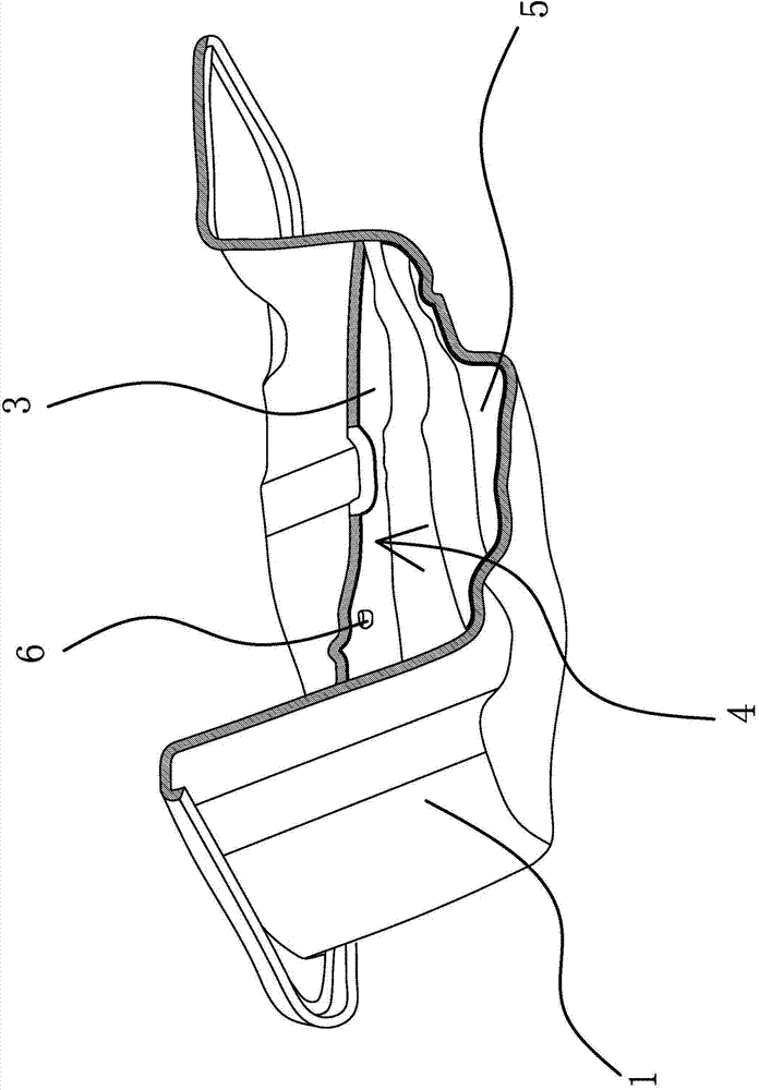
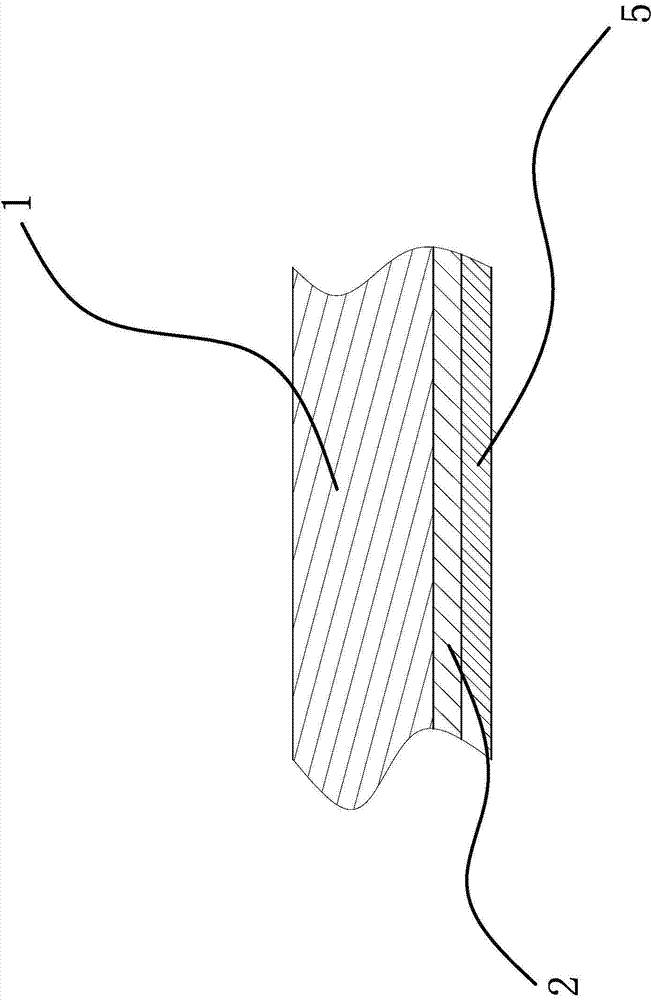
[0029] Such as figure 1 , figure 2 and image 3 As shown, a magnetic oil pan for automobiles, the inner wall of the oil pan 1 is provided with a magnetic layer 2, the upper part of the oil pan 1 is provided with an oil baffle plate 3, and an oil baffle plate 3 is provided between the oil baffle plate 3 and the bottom of the oil pan 1. The magnetic layer 2 is distributed on the bottom and side walls of the oil pan 1 for shielding the magnetic field generated by the magnetic layer 2; the magnetic layer 2 covers the entire bottom of the oil pan 1, and the side walls of the oil pan 1 are partially covered with The magnetic layer 2, the vertical height of the side wall of the oil pan 1 covered with the magnetic layer 2 is 5cm to 15cm; the magnetic layer 2 covers the inner wall of the oil pan 1 in a large area, which can strengthen the magnetization effect of the magnetic layer 2 on the oil and absorb iron The magnetic layer 2 is permanent magnet powder electroplated or sprayed o...

Embodiment 2

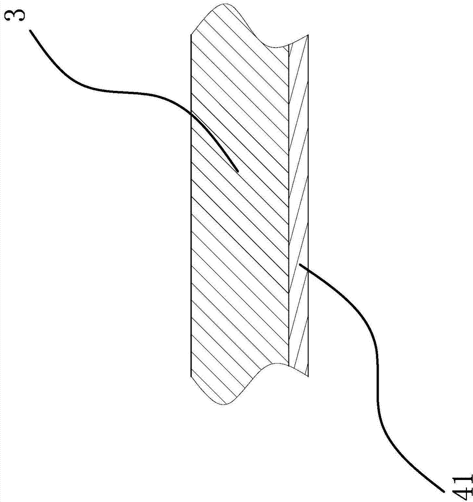
[0036] Such as Figure 4 As shown, the content of this embodiment is roughly the same as that of Embodiment 1, the difference is that the antimagnetic structure 4 includes a baffle 42 fixed on the inner wall of the oil pan 1, and the baffle 42 is located at the oil return hole 6 of the oil baffle 3 Below, the lower surfaces of the oil baffle 3 and the baffle 42 are pasted with a foil shielding layer 41, and the foil is low-carbon iron; this solution can eliminate the possibility of magnetic flux leakage through the oil return hole 6.


PUM

PropertyMeasurementUnit
Thicknessaaaaaaaaaa
Thicknessaaaaaaaaaa
Vertical heightaaaaaaaaaa

Abstract

The invention provides an automobile magnetic oil pan, and belongs to the technical field of engines. The automobile magnetic oil pan solves the technical problems that an existing oil pan is poor in scrap iron removal effect, cannot perform magnetization on engine oil and the like. According to the automobile magnetic oil pan, a magnetic layer is arranged on the inner wall of the oil pan, an oil baffle is arranged on the upper portion of the oil pan, and an antimagnetic structure used for shielding a magnetic field generated by the magnetic layer is arranged between the oil baffle and the bottom of the oil pan. The automobile magnetic oil pan has the advantages of being good in scrap iron removal effect, can perform magnetization on engine oil and the like.

Description

technical field [0001] The invention belongs to the technical field of engines and relates to an automobile magnetic oil pan. Background technique [0002] The oil pan is located at the lower part of the engine and can be disassembled to seal the crankcase as an oil storage tank. The oil sump is the lower half of the crankcase, also known as the lower crankcase. Its function is to close the crankcase as the outer shell of the oil storage tank, prevent impurities from entering, and collect and store the lubricating oil that flows back from the friction surfaces of the engine. Part of the heat prevents the lubricating oil from oxidizing. [0003] At present, more than 90% of the main working parts of the engine, such as crankshaft, camshaft, rocker arm, piston ring and various bearings, are made of ferrous materials. When the engine is working, these moving parts will inevitably wear and tear, and the metal debris produced by the wear will circulate with the oil, causing con...

Claims


Application Information

Patent Timeline
IPC IPC(8): F01M11/00F02F7/00
Inventor 胡蓉蓉王德远杨陈沈源由毅吴成明冯擎峰
Owner ZHEJIANG GEELY AUTOMOBILE RES INST CO LTD
Why Eureka
Try Eureka