Load-Based Fuel Economy Control System

A fuel and load technology, applied in engine control, machine/engine, mechanical equipment, etc., can solve problems such as human errors in fuel economy models

Active Publication Date: 2017-08-25
酷敏斯IP公司
View PDF6 Cites 0 Cited by
  • Summary
  • Abstract
  • Description
  • Claims
  • Application Information

AI Technical Summary

Problems solved by technology

More specifically, user-selected fuel economy modes are subject to human error and poor judgment

Method used


Image

  • Load-Based Fuel Economy Control System
  • Load-Based Fuel Economy Control System
  • Load-Based Fuel Economy Control System

Examples


Embodiment Construction

[0022] Reference throughout this specification to "one embodiment," "an embodiment," or similar language means that a particular feature, structure, or characteristic described in connection with the embodiment is included in at least one embodiment of the present disclosure. Appearances of the phrases "in one embodiment," "in an embodiment" and similar language throughout this specification may, but do not necessarily, all refer to the same embodiment. Similarly, the term "implementing" means that an implementation has a particular feature, structure, or characteristic described in connection with one or more embodiments of the present disclosure, whereas the absence of a related expression indicates that an implementation may be associated with one or more embodiments .

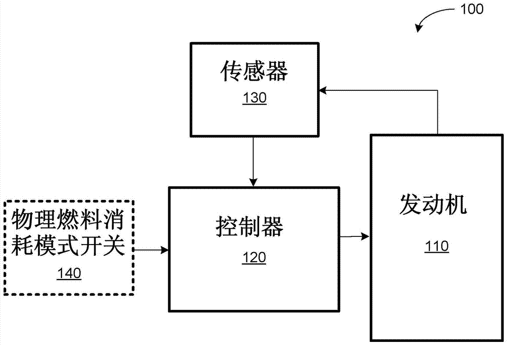
[0023] According to figure 1In one embodiment shown in FIG. 1 , an internal combustion engine system 100 includes a fuel-powered internal combustion engine 110 . Although not shown, engine system 100 may ...


PUM


Abstract

According to one embodiment, a device for controlling fuel consumption in an internal combustion engine system of a vehicle capable of carrying a load comprises a mass module configured for determining the mass of the vehicle. The apparatus also includes a fuel consumption mode selection module configured to select a fuel consumption mode for operation of the internal combustion engine based on the determined mass of the vehicle. Additionally, the apparatus includes a fuel command module configured to generate a fueling command based on the selected fuel consumption mode.

Description

technical field [0001] The present disclosure relates generally to controlling the fuel economy of an internal combustion engine system of a vehicle, and more particularly to controlling the fuel economy of an internal combustion engine system based on the mass of a load being transported by the vehicle. Background technique [0002] In view of stricter regulations and higher oil prices, the automotive industry is aiming at reducing the fuel consumption of vehicles powered by internal combustion engines. However, one known tradeoff associated with reducing fuel consumption (eg, improving fuel economy) is a proportional reduction in performance (eg, power). While some prefer improved fuel economy over performance, others desire performance over fuel economy. Consequently, recent advances in the automotive industry attempt to satisfy the need for both types of driving preferences by reducing fuel consumption while minimizing performance loss. [0003] Some engine systems are...

Claims


Application Information

Patent Timeline
Patent Type & Authority Patents(China)
IPC IPC(8): F02D29/02
Inventor B-C·张L-X·彭T·王Z-L·江
Owner 酷敏斯IP公司
Why Eureka
Try Eureka