Ball joint

A ball and socket joint and ball stud technology, applied in pivot connections, shafts and bearings, mechanical equipment, etc., can solve problems such as the inability of vibration dampers to work effectively

Inactive Publication Date: 2014-02-12
KAYABA SYST MACHINERY
View PDF2 Cites 0 Cited by
  • Summary
  • Abstract
  • Description
  • Claims
  • Application Information

AI Technical Summary

Problems solved by technology

[0009] However, the vibration damper is not a type of vibration damper that operates by an axial force like a liquid damper, but a type of vibration damper that generates a torque around the axis of the damper like an inertial mass damper, for example. In the case of a damper, that is, a vibration damper that operates by transmitting ...

Method used


Image

  • Ball joint
  • Ball joint
  • Ball joint

Examples


Embodiment Construction

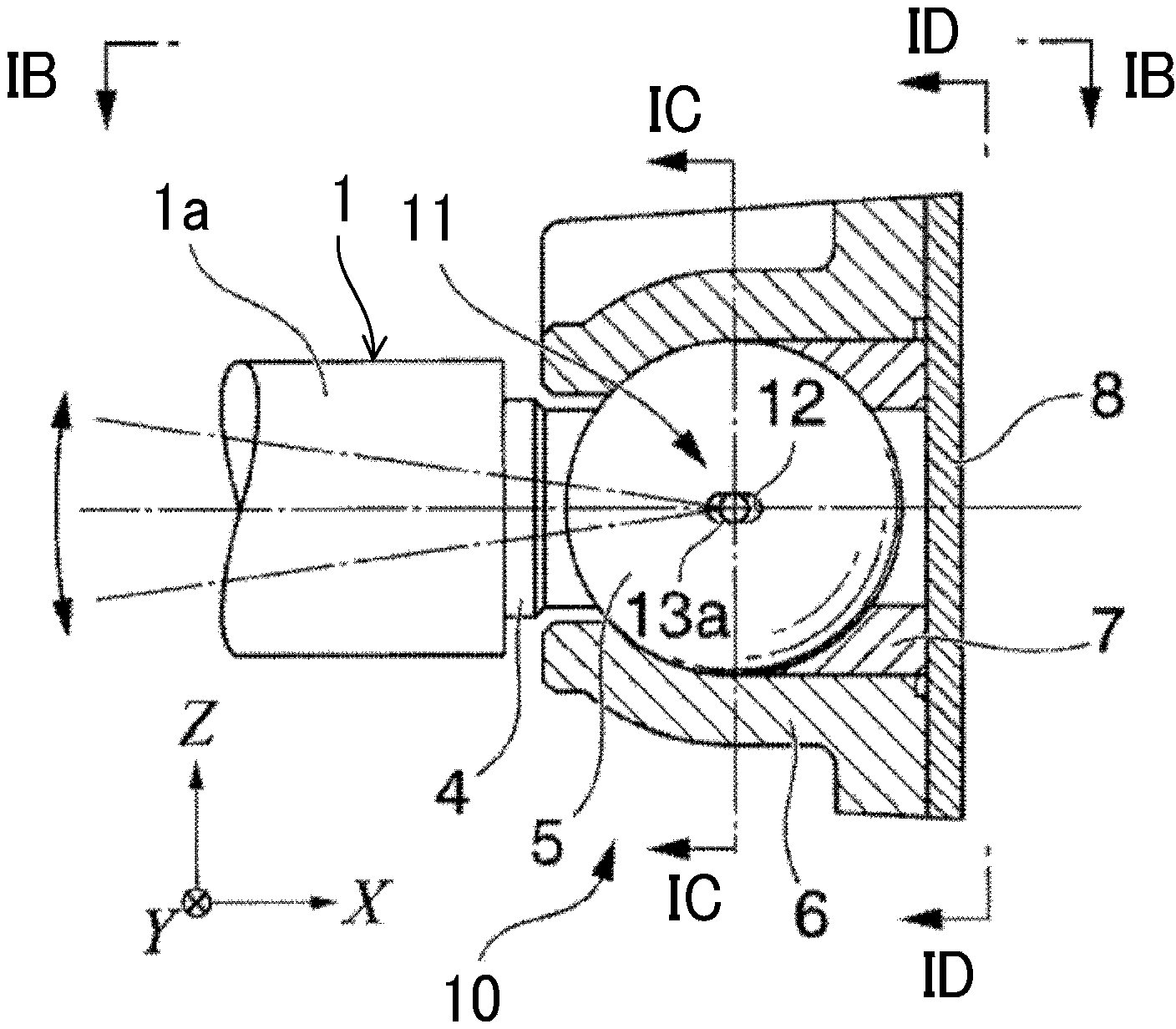
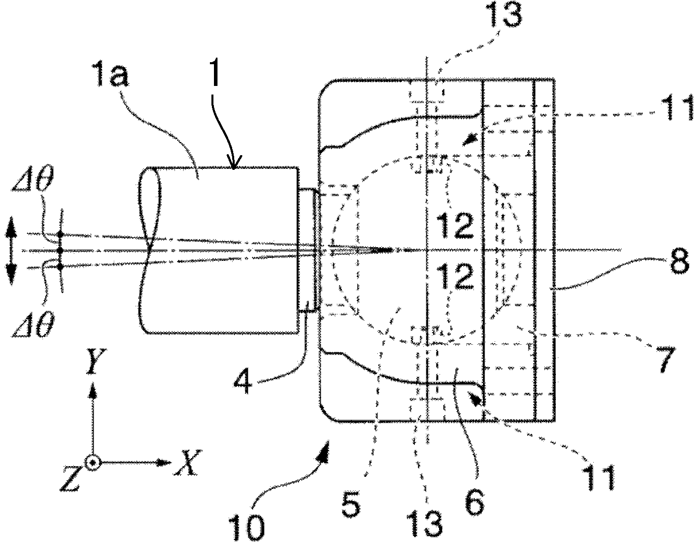
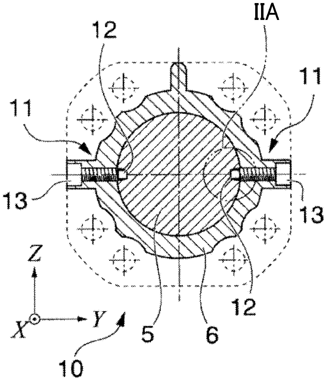
[0026] Figure 1A ~ Figure 1D It is a figure which shows the ball joint 10 of this embodiment.

[0027] The ball joint 10 of this embodiment is used to install the vibration damper 1 on a structure. The ball joint 10 includes: a ball stud 4 for connecting the rod 1a of the vibration damper 1; a spherical head 5 provided at the top end of the ball stud 4; The spherical head 5 is accommodated in a state where the spherical head 5 is relatively rotated; the bracket 7 supports the spherical head 5 in the ball housing portion 6 and restrains the relative movement of the ball stud 4 in the axial direction; and the plate 8 , which is installed at the rear of the ball storage portion 6. Accordingly, the ball joint 10 allows the ball stud 4 to swing in any direction relative to the ball housing portion 6 while restricting the relative movement of the ball stud 4 in the axial direction.

[0028] The ball joint 10 further includes a rotation restricting mechanism 11 for restricting th...


PUM


Abstract

A ball joint (10) includes: a spherical head portion (5) provided in a leading end of a ball stud (4); a ball retainer (6) that houses the spherical head portion (5) in a relatively rotatable state; a holder (7) that supports the spherical head portion (5) and restrains relative displacement in a shaft axis direction of the ball stud (4); and a rotation limiting mechanism (11) that limits relative rotation of the spherical head portion (5) against the ball retainer (6). The rotation limiting mechanism (11) has an engagement hole (12) formed in the spherical head portion (5) and a limiting bolt (13) that inserted into the engagement hole (12). The engagement hole is formed as an oval hole having a major axis extending in the shaft axis direction of the ball stud and a minor axis. The minor axis is equal to a diameter of the engagement protrusion (13a).

Description

technical field [0001] The invention relates to a ball joint. Background technique [0002] A ball joint is a type of universal joint, and is a joining part for pivotally connecting various members to each other so that they can freely swing in any direction (free relative rotation). Ball joints are used in various fields such as suspension mechanisms for vehicles. [0003] JP2005-121141A discloses that a ball joint is used instead of a clevis when installing a vibration damper on a structure such as a building. Figure 5A and Figure 5B It is a diagram showing a state where a liquid damper as a vibration damper 101 is installed on a structure 102 (a support, a column, a beam, etc.) of a structure to be damped using a ball joint 103 . [0004] Such as Figure 5B As shown, the ball joint 103 includes: a spherical head 105, which is arranged on the top end of the ball stud 104; a ball receiving portion 106, which is used to accommodate the spherical head 105; a bracket 107,...

Claims


Application Information

Patent Timeline
IPC IPC(8): F16C11/06
CPCF16C11/0647F16C11/06F16C11/0623F16C11/0642F16C11/106
Inventor 矶田和彦冈本真成火箱义文
Owner KAYABA SYST MACHINERY
Why Eureka
Try Eureka