Supercharge Your Innovation With Domain-Expert AI Agents!

Valve device

A technology of valve device and valve closing, which is applied in the direction of valve device, valve operation/release device, valve lift, etc., and can solve the problem that the learning process cannot be executed, etc.

Inactive Publication Date: 2017-03-01
DENSO CORP
View PDF9 Cites 0 Cited by
  • Summary
  • Abstract
  • Description
  • Claims
  • Application Information

AI Technical Summary

Problems solved by technology

The above learning process cannot be performed because the angle in the clearance range is different from the full closure angle

Method used


Image

  • Valve device
  • Valve device
  • Valve device

Examples


no. 1 example

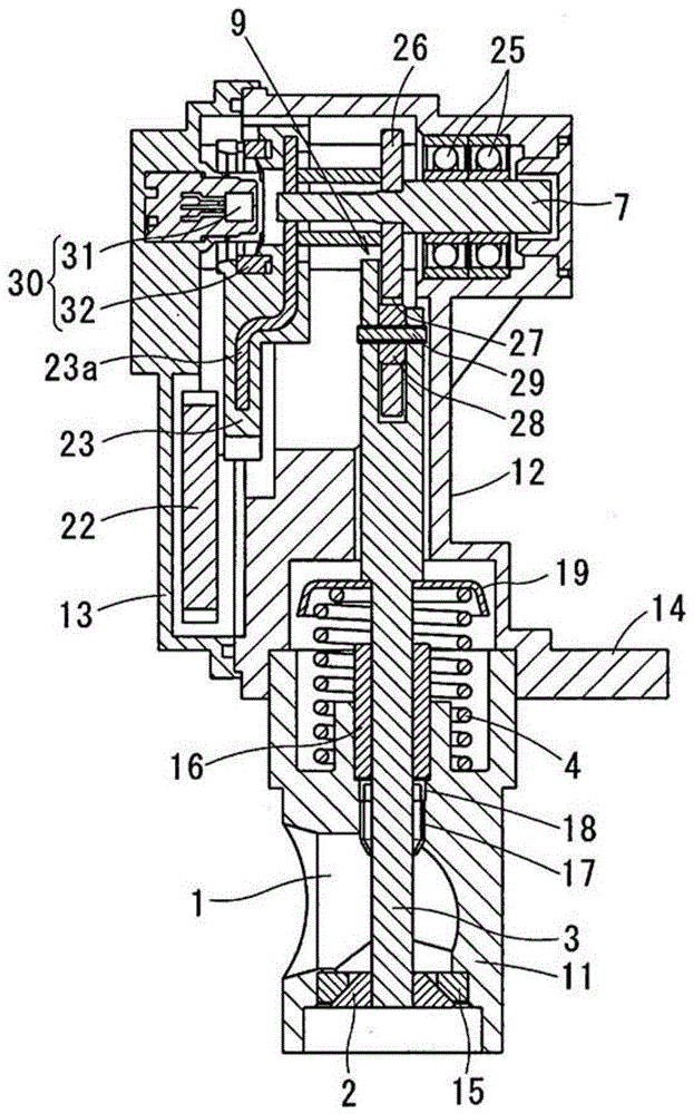
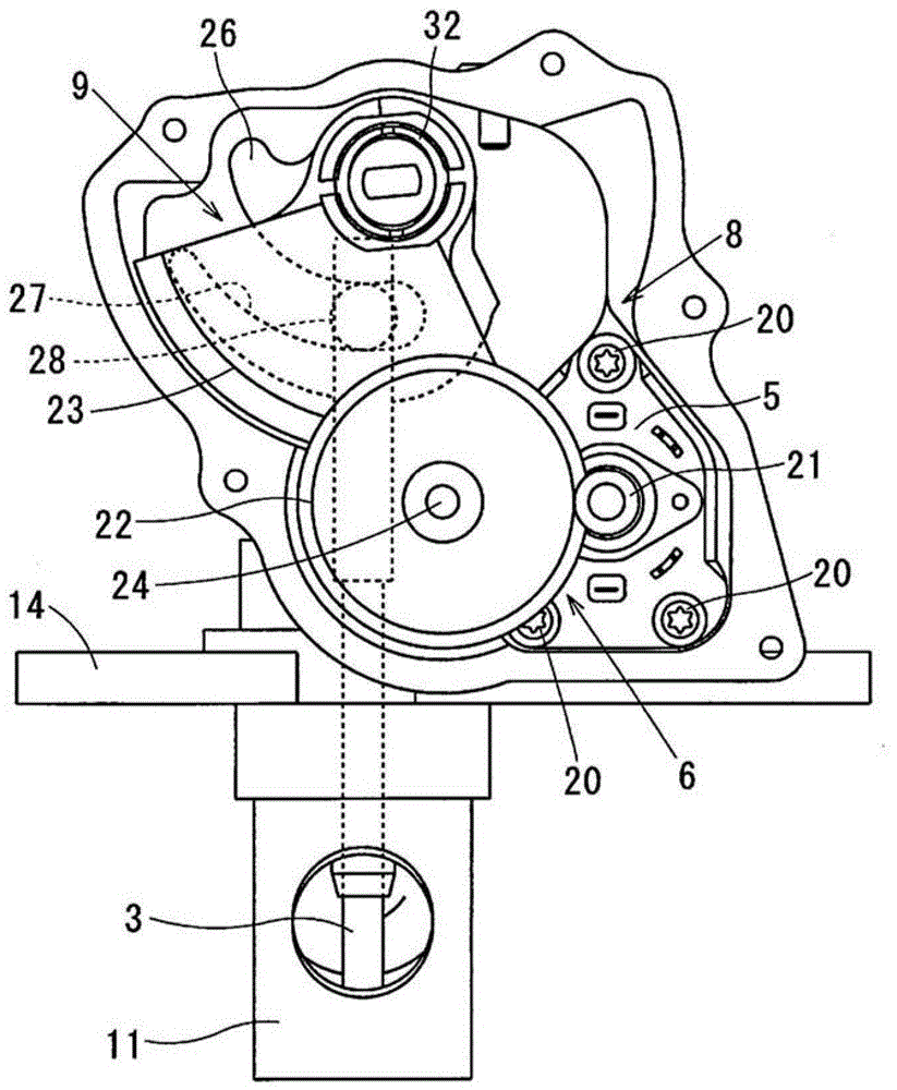
[0025] refer to Figures 1 to 3 , the first embodiment will be described below. In the following description, figure 1 The upper part of is called upper, and figure 1 The lower part is called the lower part. However, this up and down direction does not correspond to the installation direction of the vehicle. In this embodiment, the valve device is applied to an EGR valve of an exhaust gas recirculation system (EGR system).

[0026] The EGR system is a known system in which a part of the exhaust gas is returned to the intake duct as EGR gas. The EGR system has an EGR passage 1 through which a part of exhaust gas flows, and an EGR valve that performs opening and closing of the EGR passage 1 and adjustment of the opening degree.

[0027] The EGR valve can be configured in the high negative pressure area of ​​the intake passage or the low negative pressure area of ​​the intake passage.

[0028] A prescribed configuration of the first embodiment will be described hereinafte...

no. 2 example

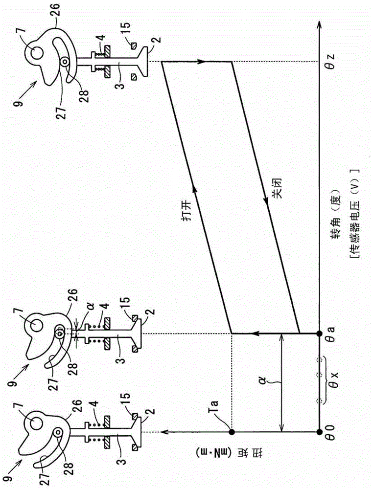
[0062] see Figure 4A , 4B and 5, the second embodiment will be described below. In the second embodiment, the same parts and components as those in the first embodiment are denoted by the same reference numerals.

[0063] First, see Figure 4A and 4B , the background of the second embodiment will be described. As described in the first embodiment, when performing the learning of the correspondence between the fully closed angle θa and the output signal of the rotational angle sensor 30, a load signal (A% of the load value) is applied to the motor 5, and the specific torque Ta A small prescribed torque is applied to the slide shaft 3 .

[0064] After performing the first operation and the second operation, such as Figure 4A As shown, when the power supply amount "A" is immediately applied to the motor 5, that is, when the load signal "A"% is immediately applied to the motor 5, each moving element (reduction gear 6, rotating shaft 7, cam disc 26) in The fully closed ang...


PUM


Abstract

A valve apparatus performs at least one of a first operation in which an electric motor is energized in a valve-close direction and a rotation shaft is rotated until its rotation is stopped and a second operation in which the electric motor is deenergized and a valve is fully closed by a biasing force of a return spring. Thereby, a rotation angle of the rotation shaft becomes a rotation-stop angle or the rotation angle becomes in the backlash range, so that a biasing force of the return spring is not transmitted to the rotation shaft. Then, the electric motor generates a specified torque, which is less than a valve-opening torque by which the valve starts opening. Thereby, a rotation angle of the rotation shaft can be stopped at a full-close angle. The full-close angle can be made correspond to an output of a rotational angle sensor.

Description

technical field [0001] The present disclosure relates to a valve arrangement that drives a valve in such a way that rotational movement of the valve is converted into linear movement of the valve. In particular, the valve device has a configuration in which a return spring biases the slide shaft in the valve closing direction. Background technique [0002] JP-2009-516134A (WO-2007-059100A1) shows a valve device that drives the valve in such a way that the rotational motion of the output shaft of the electric actuator is converted into the axial motion of the slide shaft. In the valve device, a link mechanism is utilized to convert rotational motion into axial motion. Cam grooves are formed on the cam plate that rotates with the rotary shaft. When the cam plate and the cam groove rotate, the cam follower engaged with the cam groove is driven, and thus the slide shaft moves in its axial direction. [0003] The slide shaft is biased in the valve closing direction by the bias...

Claims


Application Information

Patent Timeline
Patent Type & Authority Patents(China)
IPC IPC(8): F16K1/00F16K31/04F16K31/524F02M26/66F02M26/54
CPCF02M26/54F16K31/042F16K31/047F16K31/52408F16K37/0083
Inventor 佐佐木一司佐野亮石垣聪岛田广树
Owner DENSO CORP
Features
  • R&D
  • Intellectual Property
  • Life Sciences
  • Materials
  • Tech Scout
  • Unparalleled Data Quality
  • Higher Quality Content
  • 60% Fewer Hallucinations
Learn More